CONTROLS, INCORPORATED
CONTROL SYSTEMS & SOLUTIONS
- 9 -
9.5 Factory Settings
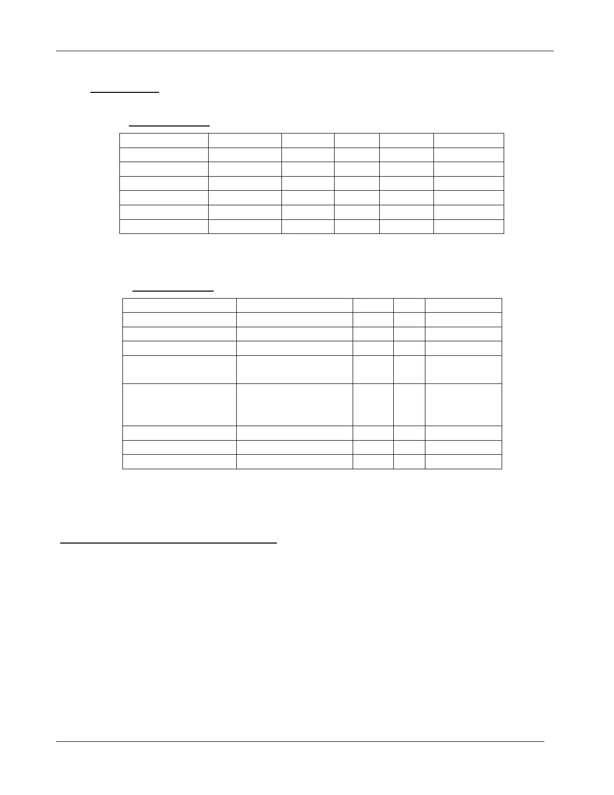
Engine Settings
Sender
Type LLPA LLA HLPA HLA
Speed MPU Na Na Na 2550
Oil Press SW to PSI 20 15 Na Na
Engine Temp SW to F Na Na 230 235
Fuel Level SW to % 20 1 Na Na
Battery Analog 12/24 15/30
LLPA = Low Level Pre Alarm HLPA = High Level Pre Alarm
LLA = Low Level Alarm HLA = High Level Alarm Na = Not Activated
Control Settings
Parameter
Setting PA A AWRO
Number of Cranks 5
Crank Duration 10 Sec
Crank Rest
Duration
10 Sec
Optional Digital
Inputs
Digital Input 1 Low Water Level Na Yes
Digital Input 2 Low Oil Level Na Yes
PA = Pre Alarm A = Alarm AWRO = Alarm While Running Only
RPM Calibration (Speed Set Procedure)
Your control system may need to be calibrated to display the correct RPM on the LCD.
1) After installing control system, start the engine and set the speed to 1500 RPM using an external
tachometer. (The EMGRT1 is shipped from factory with 30 teeth flywheel setting.)
2) Press the circuit board mounted button labeled SW3. It is located next in the upper right corner of the pcb.
3) The controller will calculate the correct number of pulses per revolution to obtain an accurate RPM display.
The crank disconnect and over speed settings are also calculated from this calibration
.