Check Recloser Ratings Prior To
Installation
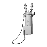
The recloser will operate effectively only when applied
within its specified ratings. Consult the following ratings
tables and compare to system characteristics at the point
of application prior to installation.
Type VXE Single-Phase Electronically Controlled Recloser Installation and Operation Instructions
10
TABLE 5
Weights and Oil Capacity of VXE15 and VXE27
Reclosers
Weight, without oil, kg (lb) . . . . . . . . . . . . . . 67 (149)
Weight, with oil, kg (lb) . . . . . . . . . . . . . . . . 89 (198)
Oil Capacity, L (gal). . . . . . . . . . . . . . . . . . . . 36 (9.5)
Weight of the Control, kg (lb) . . . . . . . . . . . . . 7.2 (16)
SPECIFICATIONS AND RATINGS
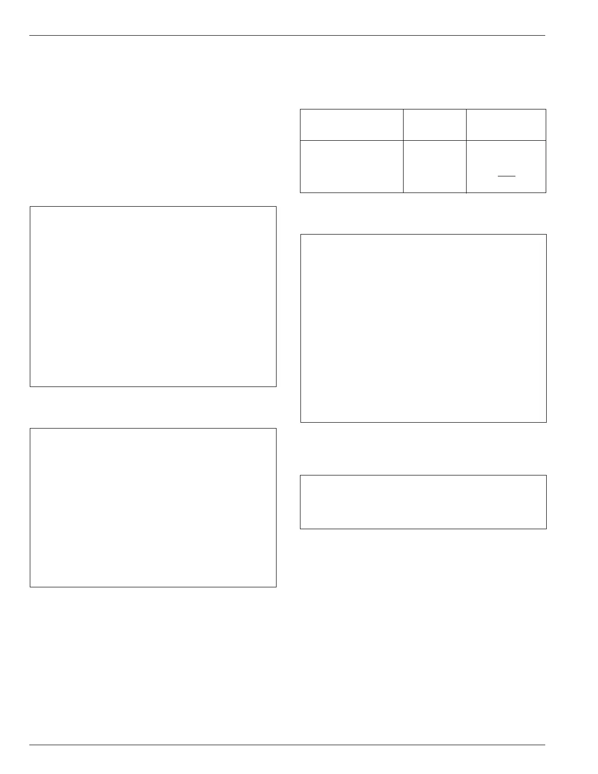
TABLE 3
Duty Cycle
Percent of Maximum Maximum Number of Unit
Circuit Interrupting X/R Ratio Operations
Rating
15-20 4 88
45-55 8 112
90-100 15 32
Total 232
TABLE 4
Mechanical Specifications
Operating Temperature (°C)
Minimum .................................................................... -30
Maximum ................................................................... +40
Closing Mechanism .................... Spring/Solenoid Operated
Opening Mechanism ................................. Spring Operated
Contact Gap (approximate) (inches) ....................... 0.4 - 0.5
Contact Close Time
Close Signal To Contact Make
(seconds) ....................................................... 0.19 - 0.24
Open Contact Travel Time
Open Signal To Contact Part
(seconds) ................................................... 0.014 - 0.022
Interrupting Time
Open Signal to Arc Extinction
(seconds) ................................................... 0.016 - 0.036
Allowable Contact Erosion (inches) .......................... 0.0625
Mechanical Life (minimum operations)......................... 2500
TABLE 1
Voltage Ratings
VXE15
Maximum Design Voltage (kV) ..................................... 15.5
Nominal Operating Voltage (kV) ............................. 2.4-14.4
Basic Insulation Level (BIL) (kV) .................................... 110
60 Hertz Withstand Voltage (kV)
Dry, one minute ........................................................... 50
Wet, ten seconds ........................................................ 45
Max RIV at 1.0 MHz/9.41 kV (µV) ................................. 100
VXE27
Maximum Design Voltage (kV) ..................................... 27.0
Nominal Operating Voltage (kV) ................................... 24.9
Basic Insulation Level (BIL) (kV) ................................... 150
60 Hertz Withstand Voltage (kV)
Dry, one minute ........................................................... 60
Wet, ten seconds ........................................................ 50
Max RIV at 1.0 MHz/23 kV (µV) .................................... 100
TABLE 2
Current Ratings
Continuous Current Rating (A)
VXE15, VXE27 .......................................................... 400
Symmetric Interrupting Current (A)
VXE15, VXE27 ....................................................... 8,000
Overload Capability VXE15, VXE27
125% - 4 Hours (A) .................................................... 500
150% - 2 Hours (A) .................................................... 600
Cable Charging Current
VXE15 (A) ..................................................................... 5
VXE27 (A) ................................................................... 25
Magnetizing Current (A)
VXE15, VXE27 ............................................................ 14
Three-Second Current, Symmetric (A)
VXE15, VXE27 ....................................................... 8,000
Surge Current (A) VXE15, VXE27 ............................. 65,000