Installing the Recloser and Control
All reclosers are carefully tested and adjusted at the fac-
tory to operate according to published data. Well
equipped test facilities, detailed testing procedures, and
thoroughly trained personnel assure accurately calibrat-
ed equipment. Each recloser leaves the factory ready for
installation. Pre-installation testing is not necessary.
Use the following procedure when installing the recloser.
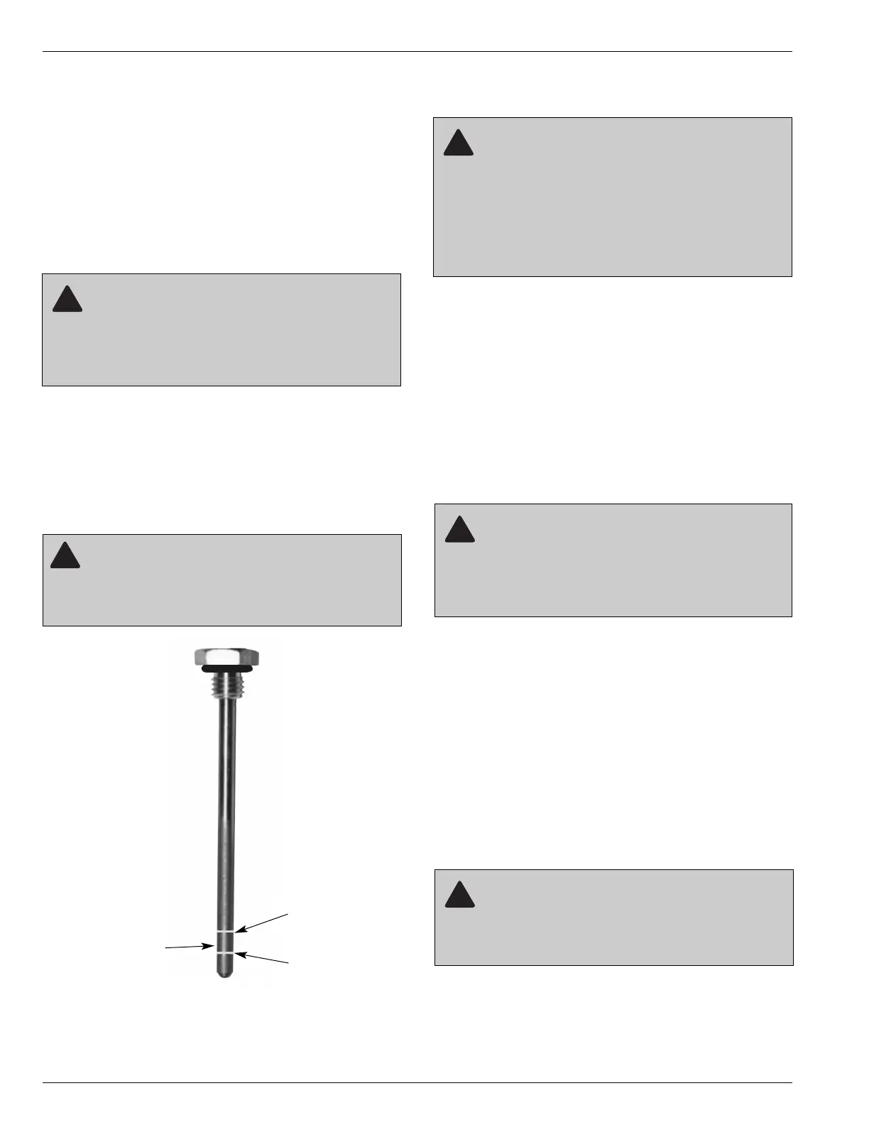
1. Check the oil level. Using the dipstick provided on
the recloser head, make sure the oil in the recloser
tank is at the proper level (Figure 8). Measure the oil
level with the dipstick completely screwed in at 25°C.
If the oil is below the minimum level, fill the recloser
with oil to the proper level, using the dipstick opening.
Do not exceed the maximum oil level, as indicated by
Figure 8.
2. Test the oil dielectric strength. If the recloser has
been stored for some time or is being relocated, per-
form a dielectric test on the oil in accordance with
ASTM-approved testing procedures.
A. On new equipment, the oil must have minimum
dielectric strength of 26 kV.
B. If the dielectric strength of the oil is less than 26 kV,
filter the oil to restore its dielectric strength to
acceptable minimum level.
3. Check the data plate ratings. Be sure the ratings
on the recloser data plates are correct for the instal-
lation.
4. Perform high-potential withstand tests. Prior to
installing the recloser, perform high-potential with-
stand tests. Refer to the Testing section of this man-
ual for high-potential withstand test procedures.
5. Program and Install the control. All VXE electronic
controls are carefully tested at the factory and
shipped with plug-in TCC cards connected and ready
for operation. Before installation, inspect the control
and make sure that all TCC components are correct
for the planned installation. Connect the control bat-
tery to the battery plug as shown in Figure 4. Make
sure that all DIP switch settings are set correctly and
that the control cable is connected between the
recloser and control.
6. Mount the recloser. Use the lifting lug located on the
head casting and follow approved procedures.
Note: It is important that the recloser be mounted on the
level to accurately check the oil.
Type VXE Single-Phase Electronically Controlled Recloser Installation and Operation Instructions
12
INSTALLATION PROCEDURE
CAUTION: This equipment relies on oil to pro-
vide electrical insulation between components.
The dielectric strength of the oil must be checked on a
regular basis, as part of the routine maintenance
inspection, to ensure that it is at or above minimum
dielectric requirements. Use of this equipment with
insulating oil that does not meet minimum require-
ments can result in internal flashovers that will damage
the equipment and can cause personal injury. G107.2