Recloser Dimensions
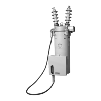
Figure 6 shows the dimensional information for VXE
reclosers. Figure 7 provides the mounting dimensions for
the control cabinet.
S280-16-1
11
NO. 6 - 350 MCM
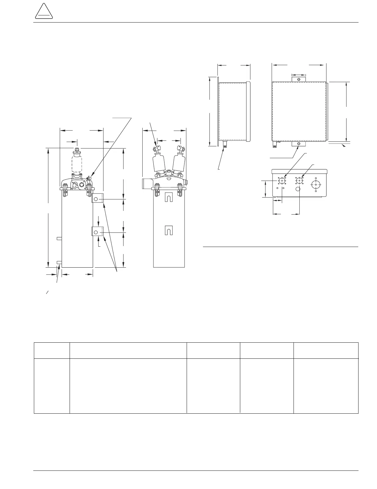
Figure 6.
Dimensions of Types VXE15 and VXE27 reclosers.
Type Bushing Type A B C
VXE15 standard 1156 (45.5) 483 (19) 270 (10.5)
VXE15 extra creepage 1237 (48.75) 564 (22.25) 283 (11)
VXE27 standard 1237 (48.75) 564 (22.25) 283 (11)
VXE27 extra creepage 1237 (48.75) 564 (22.25) 283 (11)
Dimensions of Recloser
Figure 7.
Control cabinet mounting dimensions.
12 (.47") dia.
Mtg. Hole