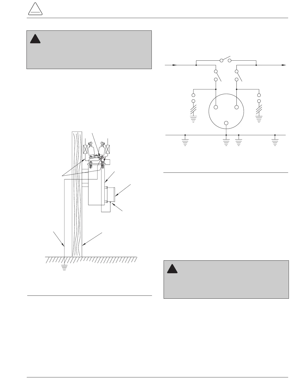
7. Ground the recloser and the control. (Refer to
Figure 9) Make ground connections to the recloser
head ground connector. It will accomodate two no. 10
through no. 2 stranded conductors. Ground the con-
trol using the ground connector provided at the bot-
tom of the electronic control cabinet for connnecting a
no. 14 through no. 4 stranded grounding cable to a
suitable ground. Make ground connections in accor-
dance with approved utility standards.
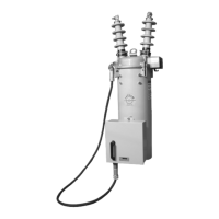
8. Make the high-voltage line connections. Connect
high-voltage lines to the recloser bushing terminals
as shown in Figure 10. The source lead must be con-
nected to the source-side bushing, which is located
adjacent to the sleet hood. To facilitate connection,
the cover of the recloser can be rotated in 90-degree
increments with respect to the tank and its mounting
bolts. The universal clamp-type terminals accept no. 6
through 350 mcm conductors.
9. Provide bypass and disconnect switches. The two
disconnect switches and the bypass switch shown in
Figure 10 are not required, but they do facilitate
maintenance.
Note: The two disconnect switches and one bypass
switch are not required, but they are highly recom-
mended.
10. Provide surge protection. Surge protection on both
sides of the recloser is advisable (Figure 10).
However, if protection is provided on only one side, it
should be located on the source side for line installa-
tions and the load side for substation installations.
Placing the Recloser in Service
Always follow locally approved procedures and safety
practices when placing the recloser in service. Be sure
that the control battery is properly connected. When the
recloser is connected and source-side high-voltage lines
are energized (by closing the source-side disconnect
switch), the recloser can be placed in service. Refer to
the connection diagram in Figure 10.
To place the recloser in service:
1. Move the yellow manual operating handle under the
sleet hood to the CLOSE position. This resets the
control and synchronizes the control to the recloser.
The recloser should immediately close.
2. Close the load-side disconnect switch and open the
bypass switch. The recloser is now in service.
Note: To remove from service, close the bypass switch,
open the recloser, and open the source and load
disconnect switches.
S280-16-1
13