496371 Issue 1 15 of 20
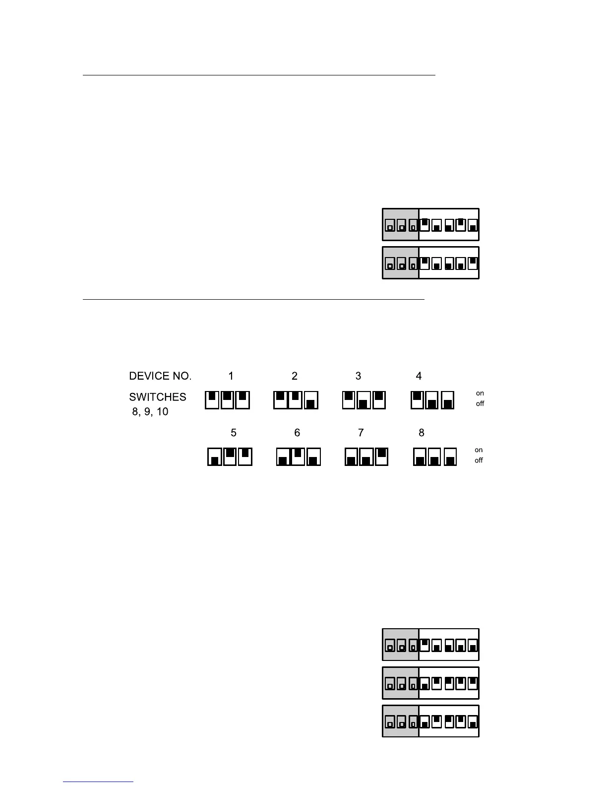
Modes 14 And 15 - Transmitter Switch Settings
At the transmitter:
• Set switches 1 to 7 to the site code
• Set switch 8 ON for device 1 or OFF for device 2.
The receiver allocates four channels to each device. Channels 1 to 4 belong
to device 1, channels 5 to 8 belong to device 2.
MODE SW SETTING
14 All Latching (2x4 Channels)
on
1 2 3 4 5 6 7 8
15 1,3,5,7 Momentary 2,4,6,8 Latching
on
1 2 3 4 5 6 7 8
Modes 16 To 18 - Transmitter Switch Settings
At the transmitter:
• Set switches 1 to 7 to the site code
• Set switches 8, 9, and 10 to the channel number as follows:
The receiver allocates one channel to each device.
The receiver activates Common Output A (and the appropriate output chan-
nel) whenever any transmitter sends an ACTIVE signal on its channel A.
The receiver allocates common output B to the channel B signals of all eight
transmitters. If the receiver receives ACTIVE signals on channel B from any
transmitter then it turns relay B ON. The receiver will only turn relay B OFF
when all eight transmitters have sent RESTORE on their B channels.
MODE SW SETTING
16 1-4 Latching, 5-8 Mmt'y (Common B)
on
1 2 3 4 5 6 7 8
17 1-4 Latching, 5-8 Mmt'y (A or B)
on
1 2 3 4 5 6 7 8
18 All Latching, Manual Clear
on
1 2 3 4 5 6 7 8
4618 Modes 14 and 15