Using a Separate Control Voltage with the New Sentronic:
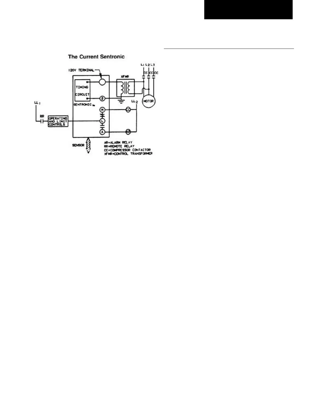
Diagram 6 shows how the current Sentronic might be used
with a voltage on its S.P.D.T. contact that is different from
the voltage that supplies its power. Any A.C. voltage up to
and including 240V might be used.
To use the Sentronic contact (S.P.D.T.) for a separate
voltage, remove the jumper between terminals "2" and "M".
In this diagram, the separate control voltage is supplied by
"LL1" and "LL2". The separate voltage powers the
compressor contactor (CC), by means of a Remote Relay.
When the Remote Relay is energized, requesting the
compressor to run, its contact, (RR), closes to deliver "LL1"
voltage to the operating and limit contacts. If the contacts
in the operating and limit circuit are closed, "LL1" voltage
energizes the compressors contactor coil (CC). When the
compressor contactor closes, it provides the power,
through a control circuit transformer (XFMR), to energize
the Sentronic. If the Sentronic trips, it contact ("L" to "M")
in the "LL1-LL2" control circuit opens to deenergize the
compressor contactor and stop the compressor. The
Sentronic contact ("L" to "A") closes to energize an Alarm
Relay (AR).
Electrical Bench Checkout Procedure
This instruction sheet describes how the Sentronic may be
easily bench-checked using only a voltmeter and a
120VAC electrical extension cord.
CAUTION! Damage to the Sentronic module may result if
the “M” terminal of the Sentronic is connected to ground
or directly to a voltage line!
This test is conducted with 120VAC. A shock will result if
the Sentronic terminals are touched when the Sentronic
module is energized.
Use care whenever working with any voltage! Make sure
your electrical outlet is grounded, the electrical extension
cord used has a ground wire, and the ground wire is
connected to the grounding screw of the Sentronic.
1. Apply 120VAC power to the Sentronic module
terminals marked “120” and “L”. The Sentronic should
have a jumper in place between terminals “M” and “2”.
2. Wait two minutes, then push the Sentronic reset button
to reset the module and start the timing circuit.
3. With a voltmeter, measure line voltage (120VAC)
between the “M” terminal and the “120” terminal. It
should be the same as the electrical outlet voltage -
about 120VAC.
4. Since there is no connection made to the pressure
sensor, the module sees this as a no-oil pressure
condition. After two minutes (plus or minus 15 seconds
- dependent on 50 or 60 cycle frequency) the
Sentronic internal timer will “time-out”. The module will
trip; the circuit between “L” and “M” will open, and it
will no longer pass current to the load.
5. With the voltmeter connected to terminals “M” and
“120”, the voltage should now read zero volts because
the circuit between “L” and “M” has been opened
through the action of the electronic circuit.
6. Reset the Sentronic, then remove voltage from
terminals “120” and “L”. With a small piece of wire,
jumper the female sensor connections at the end of