Signal Pins Signal Pins
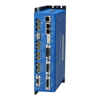
[OUT1+] J9-19 [OUT1-] J9-10
[OUT2+] J9-20 [OUT2-] J9-11
[OUT3+] J9-21 [OUT3-] J9-12
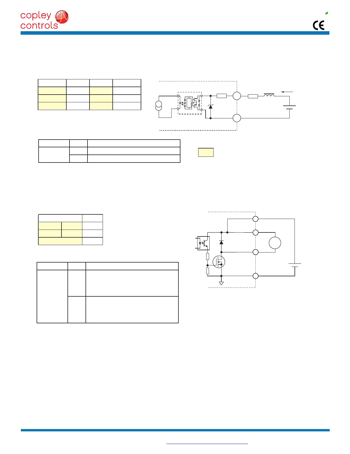
Signal Pins
BRK-A [OUT6] J5-3
BRK-B [OUT7] J5-2
BRK-24V J5-4
Input State Condition
OUT1~3
HI OutputtransistorisON,currentows
LO OutputtransistorisOFF,nocurrentows
Input State Condition
BRK-A,B
OUT6,7
HI
OutputtransistorisOFF
Brakeisun-poweredandlocksmotorshaft
Motor cannot move
BrakestateisActive
LO
OutputtransistorisON
Brakeispowered,releasingmotorshaft
Motor is free to move
BrakestateisNOT-Active
[OUT6~7]BRAKESIGNALS
[OUT1~3]SIGNALS
HI/LODEFINITIONS:[OUT6~7]BRAKE
HI/LODEFINITIONS:[OUT1~3]
Turnoff
Circuit
[OUTn-]
60mA
max
* at 24 Vdc
Vdc
J9
[OUTn+]
20
400Ω
min*
36V
ASSR-1218
+
+
J5
BRK-A,B
RTN
5
4
3,2
1
24V
24V
BRK-24V
BRK
+24V
Copley Controls, 20 Dan Road, Canton, MA 02021, USA Tel: 781-828-8090 Fax: 781-828-6547
Tech Support: E-mail: sales@copleycontrols.com, Web: http://www.copleycontrols.com Page 13 of 32
RoHS
Xenus
PLUS
2-Axis
EtherCAT
800-1782
OUTPUTS
OPTO-ISOLATEDOUTPUTS[OUT1~3]
30Vdcmax,24Vtypical
Zenerclampingdiodesacrossoutputsallowdrivingofresistive-inductive(R-L)loadswithoutexternalybackdiodes.
BRAKEOUTPUTS[OUT6,7]
Theseoutputsareopen-drainMOSFETswithaninternalybackdiodeconnectedtothe+24Vdcinput.Itcansinkupto1A
fromamotorbrakeconnectedtothe+24Vdcsupply.TheoperationofthebrakeisprogrammablewithCME 2.Itcanalso
be programmed as a general-purpose digital output.
CME2DefaultSettingforBrakeOutputs[OUT6,7]is“Brake-ActiveHI”
Active =Brakeisholdingmotorshaft(i.e.theBrake is Active)
Motor cannot move
Nocurrentowsincoilofbrake
CME2I/OLineStatesshowsOutput6or7asHI
BRKOutputvoltageisHI(24V),MOSFETisOFF
Servodriveoutputcurrentiszero
Servo drive is disabled, PWM outputs are off
Inactive =Brakeisnotholdingmotorshaft(i.e.theBrake is Inactive)
Motor can move
Currentowsincoilofbrake
CME2I/OLineStatesshowsOutput6or7asLO
BRKoutputvoltageisLO(~0V),MOSFETisON
Servo drive is enabled, PWM outputs are on
Servodriveoutputcurrentisowing
±30Vmax
±24Vtypical