Signal
J10,J11
Pin
NSK
Pin
RslvrIncA 18 A1
RslvrIncB 19 A2
RslvrIncC 20 A3
Rslvr Common 23 A4
Rslvr Abs A 9 B1
RslvrAbsB 10 B2
Rslvr Abs C 11 B3
FrameGnd 1 B5
A
NSK VR Incremental
Resolver
B
C
A
NSK VR Absolute
Resolver
B
C
J10,J11 FEEDBACK
+
-
+
-
+
-
3X 10.0`
Incremental/Absolute Select
A/D
Converter
D/A
Converter
Rslvr
Inc A
1
23
19
20
18
Rslvr Rev(+) R1
Frame Gnd (F.G.)
Rslvr
Inc B
Rslvr
Inc C
A
B
C
Rslvr
Abs A
Mux
Rslvr
Abs B
Rslvr
Abs C
10
11
9
Red
Blue
Purple
White
Black
White
Black
Red
Frame Ground
JSG Motor Resolver
0-178964-5 Connector
A4
B5
A1
A2
A3
B1
B2
B3
Copley Controls, 20 Dan Road, Canton, MA 02021, USA Tel: 781-828-8090 Fax: 781-828-6547
Tech Support: E-mail: sales@copleycontrols.com, Web: http://www.copleycontrols.com Page 14 of 32
RoHS
Xenus
PLUS
2-Axis
EtherCAT
800-1782
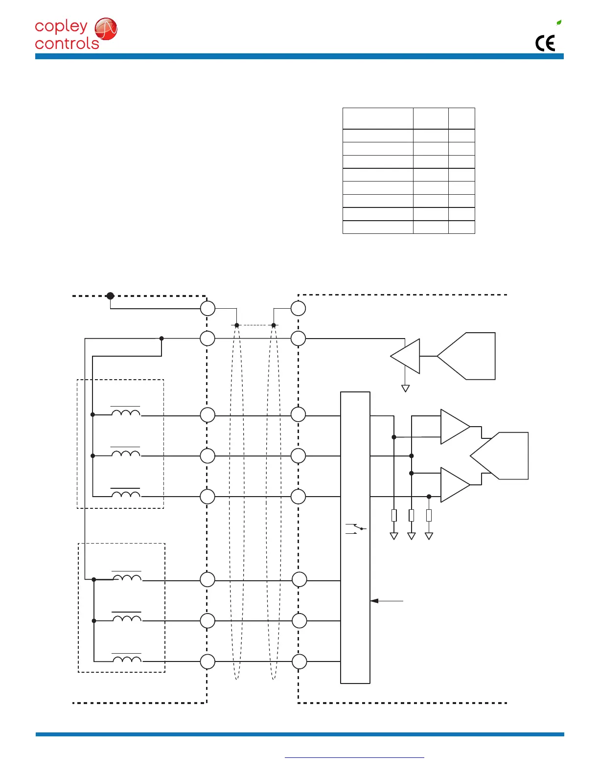
RESOLVERSIGNALSANDPINS
JSGMOTORFEEDBACKCONNECTIONS
JSGMOTORINCREMENTAL/ABSOLUTEVRRESOLVER
Connectionstotheresolvershouldbemadewithshieldedcable.Once
connected, resolver set up, motor phasing, and other commissioning
adjustments are made with CME 2 software. There are no hardware
adjustments.
When using the motor with absolute/incremental feedback, the drive
will select the absolute feedback after a reset or power-on operation.
After reading the absolute position it switches to incremental feedback
and uses that to calculate absolute position until the next reset or
power-on operation.
The motor has two Common wires, one for incremental and another
for absolute feedback resolvers. These should be wired together and
connectedtotheCommonpinofJ10,J11.