Signal
J3,J4
Pin
NSK
Pin
NSK
Color
Signal
J3,J4
Pin
NSK
Pin
NSK
Color
Mot A+ 4 1 Black Mot A- * 2 White
MotB+ 3 3 Brown MotB- * 4 Red
Mot C+ 2 5 Yellow Mot C- * 6 Green
F.G. 1 7 Shield
Signal Pin
Motemp A J10-7
MotempB J11-7
Sgnd
J10,J11
-5,16,25,26
+24V
800-1782 Motor A, B: J3,J4
F.G.
PWM
+HV
0V
+
C
B
A
4
3
2
1
C+
B+
A+
C-
B-
A-
NSK
Motor
CNA
Pin-Out
Note: Motor
windings
A-, B-, and C-
must be connected
externally.
7
5
3
1
6
4
2
NSK CNA Connector
Pin numbers
Black
White
Red
Green
Brown
Yellow
Shield
E
1
2
5
6
7
3
4
+5V
Motemp
Thermistor,
Posistor,
or switch
Signal Gnd
4.99k
10k
33n
J10,J11
Property Ohms
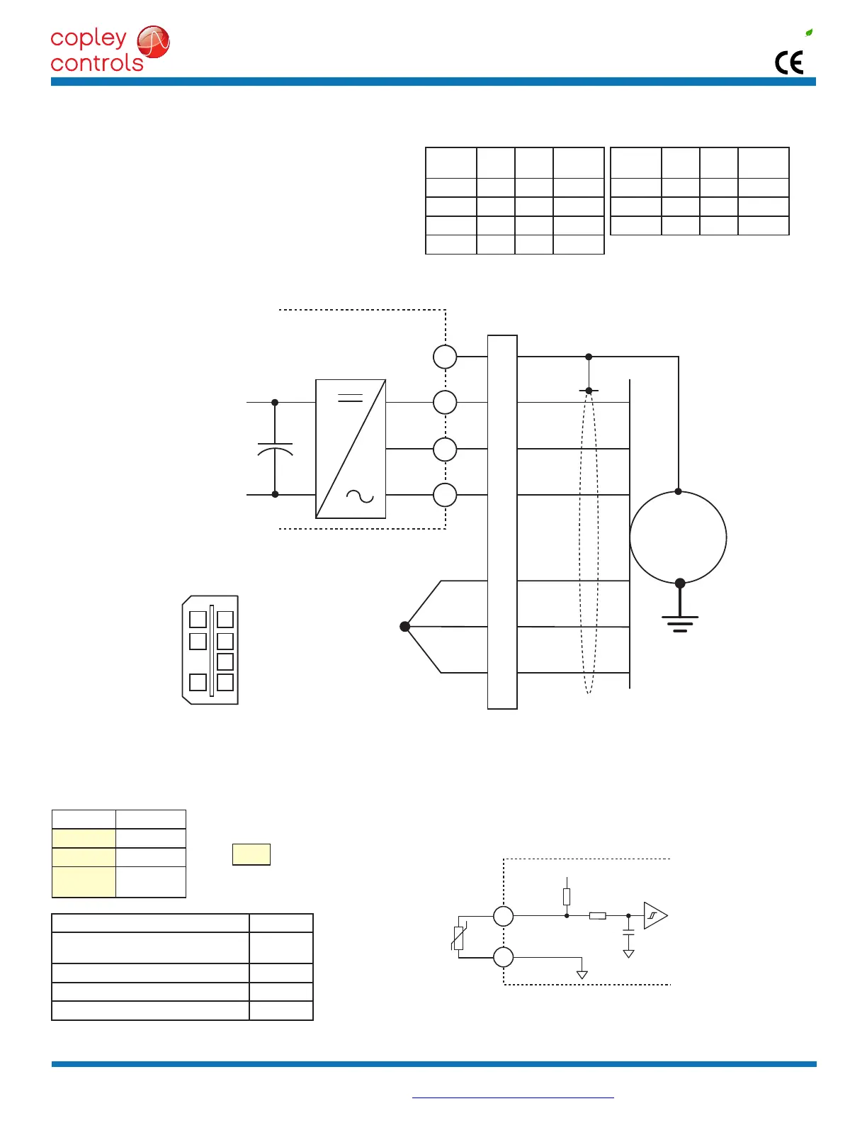
Resistance in the temperature range
20°Cto+70°C
60~750
Resistanceat85°C ≤1650
Resistanceat95°C ≥3990
Resistanceat105°C ≥12000
Copley Controls, 20 Dan Road, Canton, MA 02021, USA Tel: 781-828-8090 Fax: 781-828-6547
Tech Support: E-mail: sales@copleycontrols.com, Web: http://www.copleycontrols.com Page 15 of 32
RoHS
Xenus
PLUS
2-Axis
EtherCAT
800-1782
JSGMOTORPHASECONNECTIONS
The drive output is a three-phase PWM inverter that converts the
DCbussvoltage(+HV)intothreesinusoidalvoltagewaveforms
thatdrivethemotorphase-coils.Cableshouldbesizedforthe
continuous current rating of the motor. Motor cabling should use
twisted,shieldedconductorsforCEcompliance,andtominimize
PWM noise coupling into other circuits. The motor cable shield
shouldconnecttomotorframeandthedriveframeground(F.G.)
terminal(J3,J4-1)forbestresults.
JSGMOTORPHASESIGNALSANDPINS
MOTEMPSIGNALS
MOTOROVERTEMPINPUT
The4.99kpull-upresistorworkswithPTC(positivetemperaturecoefcient)thermistorsthatconformtoBS4999:Part111:1987(table
below),orswitchesthatopen/closeindicatingamotorover-temperaturecondition.Theactivelevelisprogrammable.
JSGMOTORPOWERANDTEMPSENSORCONNECTIONS
* These must be connected externally
+30Vmax
+24Vtypical