26
RETRAIT DE LA TÊTE DE L’ARBRE
MOTEUR – suite
NOTES :
a) Assurez-vous que les filets de la tête
ne sont pas faussés, ce qui pourrait
endommager la tête.
b) Avec les doigts, serrez la tête sur
l’arbre moteur. N’utilisez pas de clé ni
de pince.
COMMUTATEUR DE
VITESSE/COUPLE
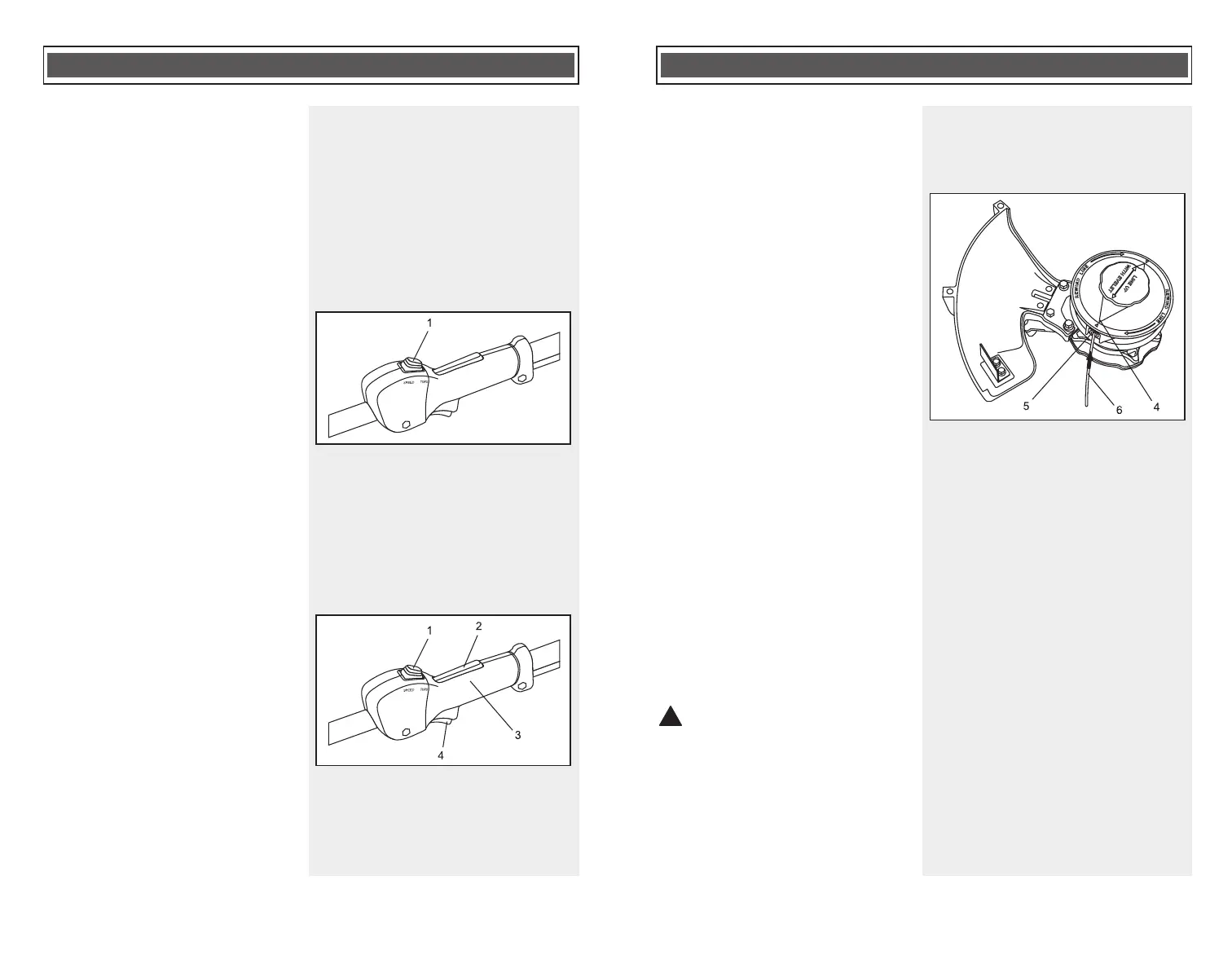
Le commutateur de vitesse/couple (1)
permet de sélectionner le mode
« couple » ou « vitesse » (Fig. 9).
Réglez le commutateur à « couple »
pour la plupart des applications. Ce
réglage fournira le couple nécessaire
pour la plupart des activités de
découpage. Ce mode permet aussi de
conserver la capacité de la pile et
d’assurer une durée de fonctionnement
plus longue. Utilisez le mode « vitesse »
pour les activités de coupe plus
intenses et lorsque vous utilisez la lame
de protection pour couper l’excès de fil
apparent.
INTERRUPTEURS DE COMMANDE
DU MOTEUR
Pour mettre en marche l’outil, appuyez
sur le bouton de verrouillage (2) qui se
trouve sur la poignée arrière (3)
(Fig. 10) et, en même temps, appuyez
sur l’interrupteur marche-arrêt (4). Pour
arrêter l’outil, relâchez le bouton et
l’interrupteur marche-arrêt.
NOTA : Si pendant que l’outil
fonctionne, vous relâchez le bouton de
verrouillage ou l’interrupteur marche-
arrêt, l’outil ARRÊTERA de fonctionner.
Pour le remettre en marche, répétez la
procédure ci-dessus.
ASSEMBLAGE ET FONCTIONNEMENT
Fig. 9
Fig. 10
RELOADING THE BUMP HEAD WITH
TRIMMER LINE – cont’d
3. Cut two 10' (3 m) lengths of high
quality .095 trimmer line.
4. Rotate the empty spool clockwise
until the arrows (4) align with the
eyelets (5) in the bump head
housing (Fig. 5).
5. Insert one end of one of the pre-cut
10' (3 m) trimmer lines (6) into one
of the eyelets as far as it will go.
Insert one end of the remaining
pre-cut trimmer line into the other
eyelet as far as it will go.
6. While holding the bump head
housing with one hand, turn the
spool clockwise to wind the trimmer
line onto the spool. Continue to turn
the spool clockwise until only 6"
(15 cm) of trimmer line is exposed
beyond the bump head housing.
NOTES:
a) When starting to wind the line onto
the spool, make sure the ends of
the line remain fully inserted into
the eyelets.
b) Excess line can be cut off with
scissors.
REMOVING THE SPOOL TO
RETRIEVE OR UNTANGLE TRIMMER
LINE
WARNING: Avoid Injury! To
avoid accidental start up: Always
remove the Power Cell before
removing or reinstalling the spool.
The trimmer line may break off at the
eyelet due to hitting debris. It may also
become entangled within the bump
head spool. In either case, you will have
to remove the spool from the bump
head as follows: