24
REINSTALLATION DE LA BOBINE VIDE
DANS LA TÊTE – suite
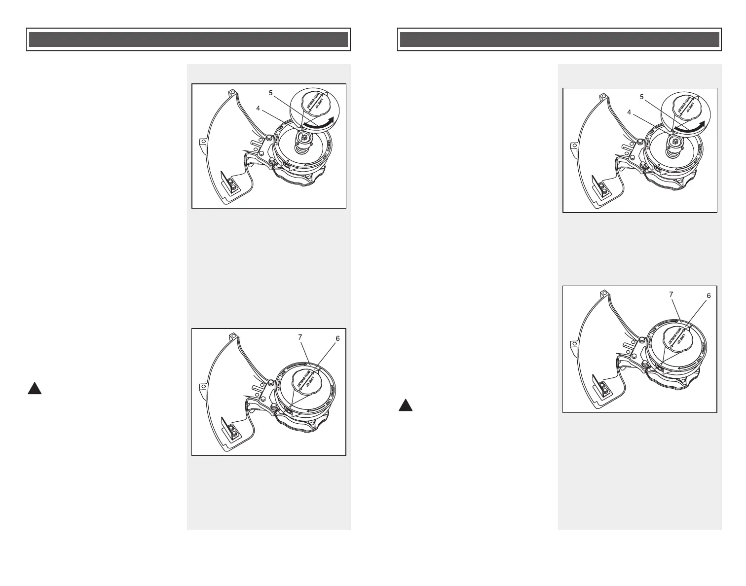
1. Alignez les quatre fentes sous la
bobine avec les quatre ergots (4)
sur l’arbre moteur et glissez la
bobine dans le carter de la tête
(Fig. 7).
2. Tenez le carter de la tête avec une
main.
3. Saisissez le bouton de la bobine
avec l’autre main et poussez
fermement sur la bobine pour
l’enfoncer dans le carter à ressort.
4. Tout en poussant fermement la
bobine dans le carter à ressort,
tournez le plus possible le bouton
de la bobine dans le sens
antihoraire (5).
NOTA :
a) La bobine tournera d’environ 15°
avant d’être bien verrouillée en
place.
b) Assurez-vous que le bord
extérieur de la bobine (6) est de
niveau avec la tête (7) (Fig. 7a).
Sinon, retirez la bobine et
réinstallez-la correctement.
c) Tirez sur la bobine pour vous
assurez qu’elle est solidement fixée
en place.
AVERTISSEMENT : Assurez-
vous que le bord extérieur de la
bobine est de niveau avec la tête et
que la bobine est solidement
verrouillée en place. Sinon, la bobine
pourrait être projetée violemment
lors de la mise en marche de l’outil,
ce qui risque de causer de graves
blessures.
5. Rebobinez le fil non endommagé
sur la bobine, comme il est indiqué
à la Fig.5.
ASSEMBLAGE ET FONCTIONNEMENT
!
Fig. 7
Fig. 7a
REINSTALLING THE EMPTY SPOOL INTO
THE BUMP HEAD – cont’d
1. Align the four slots in the spool
under side cavity with the four pins
(4) on the bump head shaft and
slide the spool into the bump head
(Fig. 7).
2. Grasp the bump head housing with
one hand.
3. Grasp the spool knob with the other
hand and press the spool firmly
into the spring loaded bump head
housing.
4. While pressing the spool firmly into
the spring loaded bump head
housing, rotate the spool knob
counter clockwise (5) until it will not
turn any further.
NOTES:
a) The spool will rotate
approximately 15° before it is fully
locked into position.
b) Make sure the outer edge of the
spool (6) is evenly positioned within
the bump head (7) (Fig. 7a). If not,
remove the spool and reinstall it
properly.
c) Pull outward on the spool to
make sure it is firmly locked into
position.
WARNING: Make sure the outer
edge of the spool is evenly
positioned within the bump head and
that the spool is firmly locked into
position. If the spool is not properly
locked into the bump head, it could
be violently thrown when the trimmer
is started and cause serious injury.
5. Reinstall any undamaged trimmer
line into the spool as outlined in
Fig.5.