STANDARD RECOMMENDED PROCEDURE 003-722 | ISSUE 4 | OCTOBER 2015 | PAGE 6 OF 10
Step 2: Follow installation instructions provided
with the UCC kit to secure the cable.
Do not tighten yet to allow for cable
adjustment if necessary.
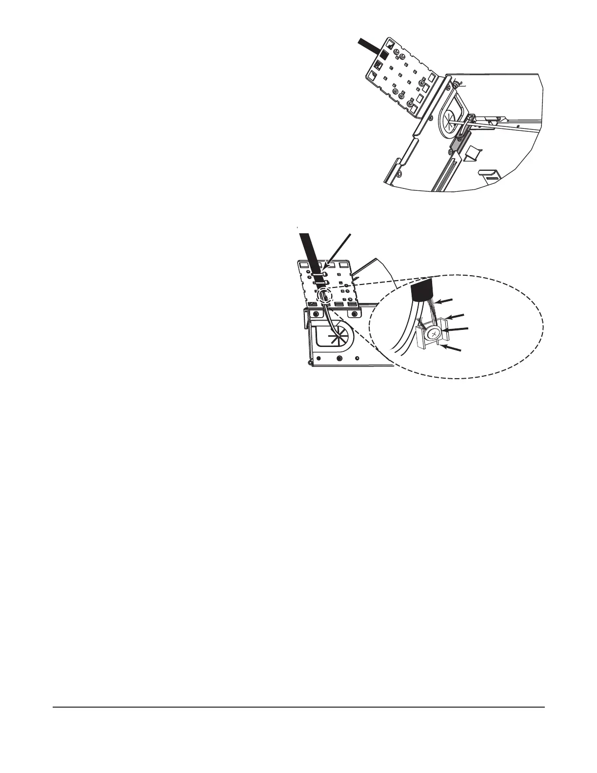
Step 3: Secure cable to cable entry plate using
a loose cable tie (Figure 7). Do not
overtighten cable tie.
4.4.2 Using Cable Ties
Step 1: Attach the cable tie to the strain-relief
bracket in two places as shown in
Figure 8.
Step 2: Allow room on the bracket to
strain-relieve the cable strength
member, if present.
Step 3: Secure cable to cable entry
plate using a loose cable tie
(Figure 8). Do not overtighten
cable tie.
Figure 8
4.4.3 Strain-relieving the Cable Central Member
Step 1: Install the U-shaped washer and the at washer on the strain-relief bracket in the
orientation shown in Figure 8 using the supplied Phillips machine screw.
Step 2: Place the central member and yarn, if present, between the U-shaped washer and
the at washer.
Step 3: Wrap yarn around the screw in a clockwise direction and under the U-shaped
washer.
Step 4: Tighten the screw.
Step 5: Trim off the excess yarn and central member.
4.4.4 Grounding Armored Cable
One grounding kit (p/n FDC-CABLE-GRND, purchased separately) is required to ground each
armored cable. Follow instructions provided with the grounding kit.
Step 2: Attach the other end of the ground wire to the equipment rack. The equipment rack
must be grounded to the primary building ground.
Step 3: Remove the paint from the frame at the grounding location to ensure metal-to-
metal contact. It is recommended to use an antioxidant on the bare metal to prevent
corrosion.
Step 4: Or, attach the other end of the ground wire to a rack-mounted grounding bus bar,
which is grounded to the primary building ground.
KPA-0152
Figure 7
Cable ties
Yarn (if present)
Y-shaped washer
Flat washer
Central member