STANDARD RECOMMENDED PROCEDURE 003-722 | ISSUE 4 | OCTOBER 2015 | PAGE 8 OF 10
4.5.2 Installing Cable Using Buffer Tube Fanout (BTF) Kits
Step 1: Terminate the bers according to the
instruction provided with the BTF kit.
Step 2: Install the fanout bracket using the
provided nuts.
Step 3: Feed the fanout body and connectors
through the entry grommet.
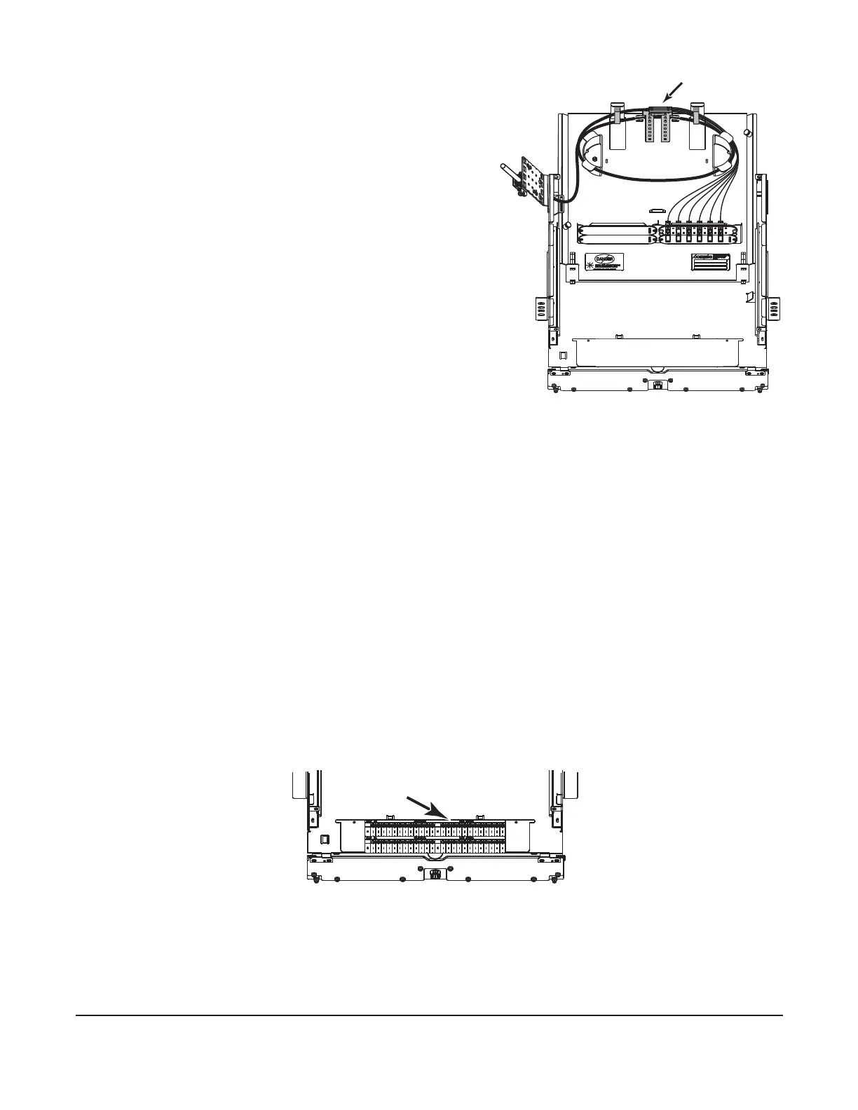
Step 4: Slide the drawer back completely and loop
the buffer tube under the fanout bracket
and around the radius control guides. Slide
the BTF truck body into the fanout bracket.
Install a cable tie to secure the fanout body
(Figure 10).
Step 5: Route the connectorized bers behind the
plastic tabs on the radius control guides.
Step 6: Cut the provided hook-and-loop strap into
two pieces and feed the two straps into the
slots at the rear of the housing. Use the
straps to secure bers as needed.
Step 7: Remove blank panels by pinching the tabs together and pulling the panel away from
the opening. Install or remove connector panels by extending or depressing the
nylon fasteners on each end of the connector panel.
Step 8: Remove dust caps from the connectors and adapters into which they will be mated.
Refer to Section 5 and clean the connector end-faces and the adapter per standard
company practices. Mate the connectors in the adapters.
4.5.3 Installing Cable Using Splice Trays
A splice tray bracket kit (p/n PC2-SPLC-6SR, purchased separately) is required to install splice
trays. Follow instructions provided with the splice tray bracket kit.
4.6 Documentation
Record ber identication information appropriately on the provided identication label
(Figure 11). Accurate recordkeeping is imperative for an organized installation.
Figure 11
4.7 Closing the Housing
Step 1: Lift up on stop latches and slide drawer toward the front of the housing to make sure
cable is not stressed. If necessary, readjust cable strain-relief to prevent stress on
bers.
KPA-0155
Figure 10
KPA-0909
Attach label here