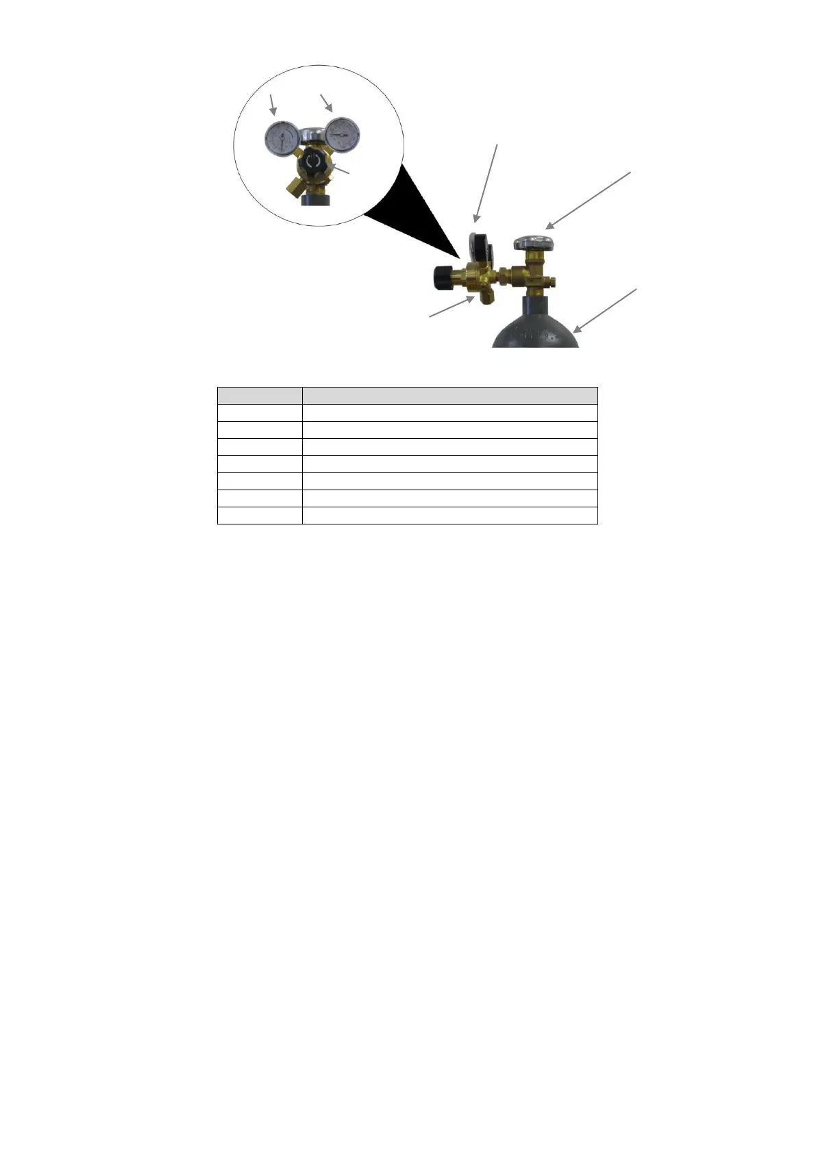
Figure 6
7.1.4 Connect the other end of the gas hose to the gas hose connection on
the supplied regulator/flow gauge. Use a wrench to snug up the
connection.
7.1.5 Before installing the regulator, it is good practice to make certain no
debris is in the gas bottle connection. Rotate the bottle so the gas
connection is not pointing toward you or any other person. Turn the
valve on the gas bottle clockwise and quickly close. This quick thrust of
gas will clear any debris in the connection. Connect the regulator to the
gas bottle connection. Use a wrench to snug up the connection.
7.1.6 Open the Gas Bottle Valve on the cylinder of gas.
7.1.7 Turn the Gas Flow Adjuster on the regulator so that the gas flow rate is
set at approximately 20 CFH. Make certain you are reading the correct
scale on the gauge.
NOTE: Slowly open the cylinder valve by turning it counter-clockwise until the cylinder pressure
gauge registers on the first gauge of the regulator. Turn the adjustment knob clockwise (right)
slowly to increase gas flow to 20 CFH. To reduce the gas flow, turn the adjustment
counter-clockwise (left). The gas valve is located on the back panel of the welder and activated
by the trigger. Gas flow should be heard when the trigger is activated. No gas flow will result in
a harsh arc with excessive spatter; a smooth weld bead will be difficult to obtain. Avoid
unnecessary gas loss by closing the tank valve when finished welding.
 Loading...