6. SETTING THE DRIVE ROLL TENSION
• Arc flash can injure eyes! To reduce the risk of arc flash, make certain that the wire
coming out of the end of the torch does not come in contact with the work piece, ground
clamp, or any grounded material during the drive tension setting process or arcing will
occur.
6.1 Press the trigger on the torch.
6.2 Turn the drive tension adjustment knob clockwise until the wire seems to feed
smoothly without slipping.
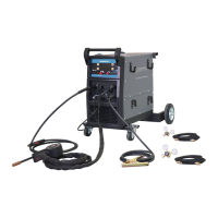
7. GAS INSTALLATION
Shielding gas cylinders and high-pressure cylinders can explode if damaged, so treat them
carefully.
• Never expose cylinders to high heat, sparks, open flames, mechanical shocks or arcs.
• Do not weld on the cylinder.
• Always secure cylinder upright to a cart or stationary object.
• Keep cylinders away from welding or electrical circuits.
• Use the proper regulators, gas hose and fittings for the specific application.
7.1 Polarity Changing - When MIG wire is used, shielding gas is required and the polarity
on this unit needs to be electrode positive.
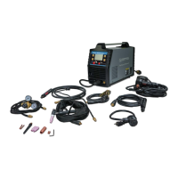
7.1.1 Electrode Positive for MIG Welding - The Weld Power Cable (see
Figure 8) should be connected to the positive (+) weld output
connection on the front of the machine. The ground cable would then
be connected to the negative (-) weld output connection.
7.1.2 Electrode Negative for Flux Core Welding - The Weld Power Cable
should be connected to the negative (-) weld output connection on the
front of the machine. The ground cable would then be connected to the
positive (+) weld output connection. Refer to the polarity setting label
inside the wire compartment.
7.1.3 Connect one end of the gas hose to the gas hose connection on the
back of the welder. Use a wrench to snug up the connection.
 Loading...