7.1.8 Gas Selection
Different materials require different shielding gases when MIG welding.
(Refer to the set-up chart inside the wire feed compartment.)
Mild Steel: Use 75% Argon and 25% CO2 for reduced spatter and
reduced penetration for thinner materials. DO NOT USE Argon gas
concentrations higher than 75% on steel. The result will be extremely
poor penetration, porosity, and brittleness of weld.
Mild Steel: Use CO2 for deeper penetration but increased spatter. (A
CO2 regulator adapter will be needed.)
Stainless Steel: Use a mixed gas consisting of Helium, Argon, and
CO2.
Aluminum or Bronze: Use 100% Argon.
ASSEMBLY
Electrical Shock
• Electric shock can kill! Always turn the POWER switch OFF and unplug the power cord
from the AC power source before installing wire.
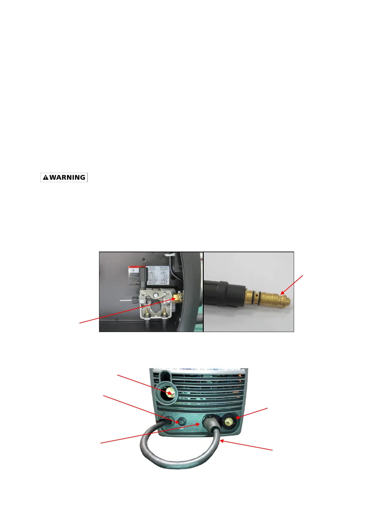
MIG TORCH ASSEMBLY
1. Locate the wing nut retaining bolt inside the front panel on the Drive System (Figure 7). Loosen
the retaining bolt.
Figure 7
2. Make note of the retaining groove on the back end of the MIG torch (Figure 7).
Figure 8