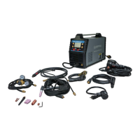
3. Insert the back end of the MIG torch into the MIG socket on the front of your machine (Figure 8).
Make certain to completely slide the torch all the way in. Slightly twist to assist with pushing the
torch to the back of the receptacle. The retaining bolt can then be tightened, making certain the
bolt sets down into the retaining groove on the back of the MIG torch.
4. Connect the 5-Pin trigger connection on the MIG torch to the 5-Pin trigger receptacle on the front
panel (Figure 8).
5. Connect the ground cable to the negative (-) weld output connection for MIG welding. If welding
with self-shielded flux core, connect the ground cable to the positive (+) weld output connection
and move the Weld Power Cable to the negative (-) weld output connection.
6. Follow the Wire Feed Welding Set-up instructions in the Operating section.
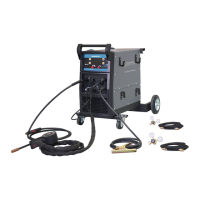
SPOOL GUN ASSEMBLY (OPTIONAL WITH MMWMP242DVIB)
1 This unit is set-up to accept the MMWEZFSG2 gun only.
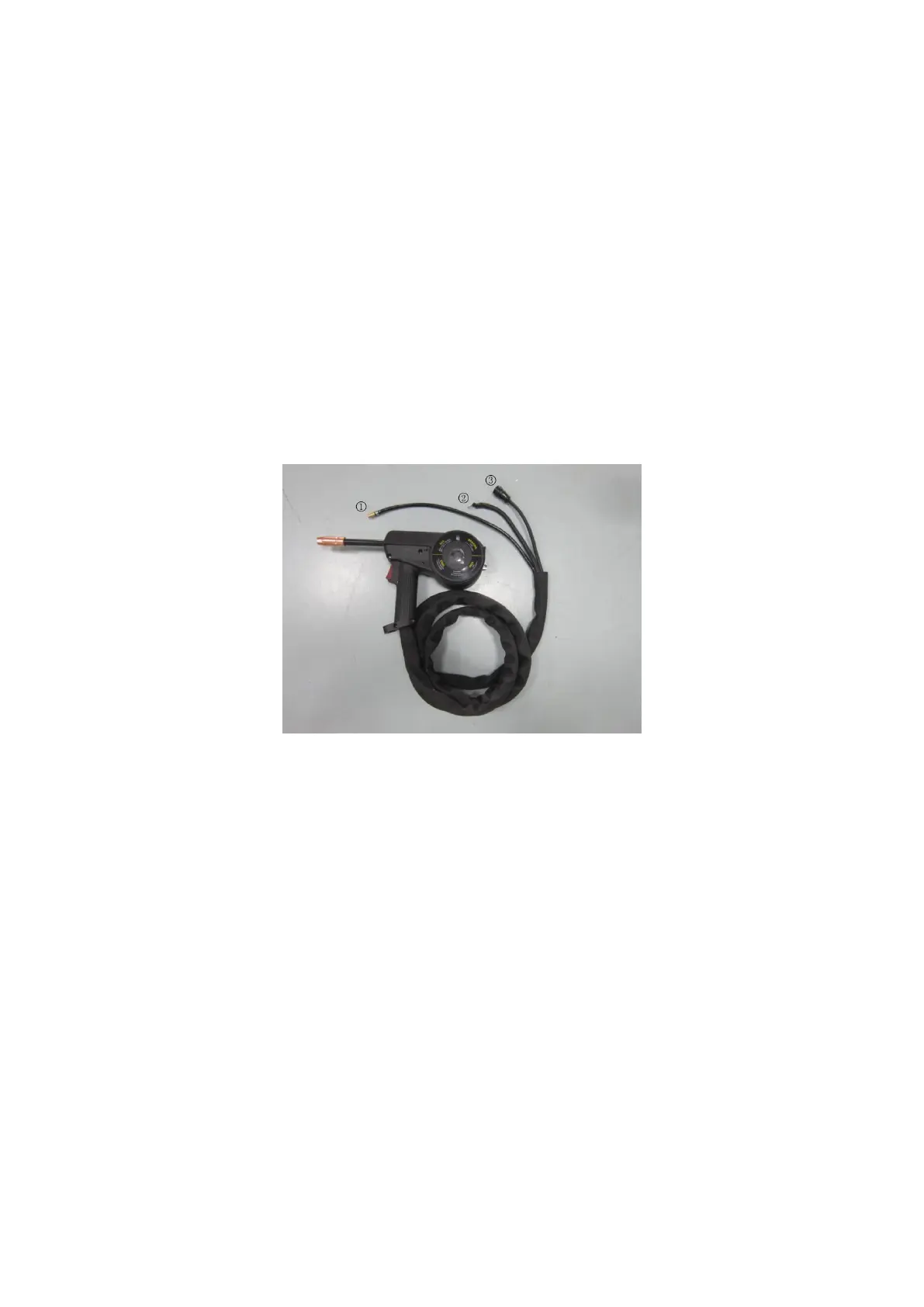
2 The MMWEZFSG2 has three connection points at the back of the spool gun. (1) The gas
connection is a slide on quick connector. (2) The weld power connection has a round ring
connection. (3) The trigger connection is the 5-Pin snap on connector.
3 We recommend removing the MIG torch when the Spool Gun is connected to avoid accidental
arcing. Loosen the wing nut retaining bolt and slide the MIG torch out of the front of the machine.
Disconnect the 5-Pin trigger connection on the front of the machine.
4 Carefully slide the gas connector and the weld power connection through the weld cable access
opening in the front of the machine (Figure 10).
 Loading...