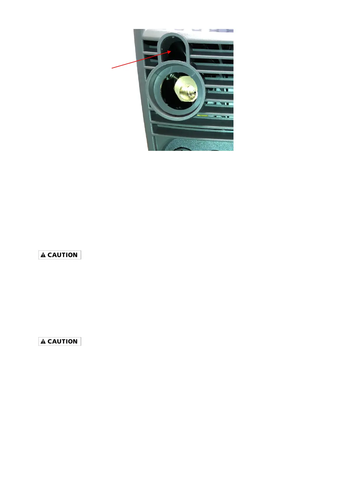
Figure 10
5 Open the wire compartment door.
6 Connect the gas connection quick connector to the gas connector (1) on the back panel of the
wire compartment.
7 Connect the weld power connection to the bolt on the top of the MIG connector (2).
8 Connect the 5-Pin trigger connector to the 5-Pin receptacle on the front of the machine (3).
9 See step 11 of WIRE FEED WELDING SET-UP in the Operating Instructions section
DC STICK WELDING ASSEMBLY
- Be aware that the ELECTRODE HOLDER will be electrically HOT when the Input Power Switch on the
welder is turned ON.
1. Install the ground cable quick connector to the negative (-) Weld Output Connector (Figure 8).
2. Secure the ground clamp to the work piece.
3. Install the electrode cable quick connector to the positive (+) Weld Output Connector.
4. Follow the STICK WELDING SET-UP instructions in the Operating Instructions section.
OPTIONAL TIG TORCH ASSEMBLY (OPTIONAL WITH MMWMP242DVIB)
- Be aware that the TIG TORCH will be electrically HOT when the Input Power Switch on the welder is
turned ON.
1. Remove the ground cable and the electrode holder from the weld output connections. Install the
ground cable to the positive (+) weld output connection (Figure 8).
2. Secure the ground clamp to the work piece.
3. Connect a regulator to a bottle of ARGON gas. Then connect the gas connection from the TIG
torch to the regulator.
4. Connect the TIG torch weld cable to the negative (-) weld output connection.
5. Set the desired amperage on the amperage control knob on the front panel of the welder.
6. Turn on the input power switch on the welder.
7. Turn on the regulator on the bottle of shielding gas and adjust the regulator to approximately 20
CFH. Open the shielding gas valve on the torch to start the flow of shielding gas.