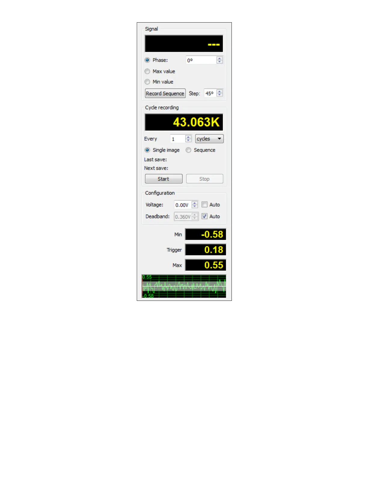
Once running, the cameras will be triggered at the specified phase (0º, to start). To change the phase that you are viewing,
you can select a different value in the Phase control. The step for this control is determined by the Step control.
A sample waveform is displayed at bottom. The red vertical line in the waveform indicates the current trigger phase. The
white horizontal line is the trigger voltage, and the white range is the current deadband.
Above the waveform display are indicators for the signal minimum (Min), maximum (Max), and the voltage at the trigger
phase (Trigger). These values are scaled according to the scale and offset for channel 0, which can be edited from the
Analog Data dialog.
To the top right, a counter displays the number of cycles that have passed since the control was opened. This count is an
estimate based on the measured frequency; it should be quite accurate but is not an exact count of zero crossings. To reset
this count, right-click on the value.
By default, the voltage and deadband are continuously and automatically adjusted. If you want to select a specific trigger
voltage and deadband, you can clear the “Auto” checkbox and select the desired parameters.
 Loading...