CPI Canada Inc. Installation 2
2.8.5 Configuring dual-speed starter 901297-15 / 901298-15
Dual-speed starter part number 901297-15 / 901298-15 is a special configuration in which the low-speed
phase shift capacitors may be set to 15.5 uF or 28 uF. The 15.5 uF setting is intended for use in
installations where low-speed operation of CGR (GE) Statorix tubes is required. The high-speed
capacitance is automatically selected to either 3 uF or 6 uF according to the DIP switch setting.
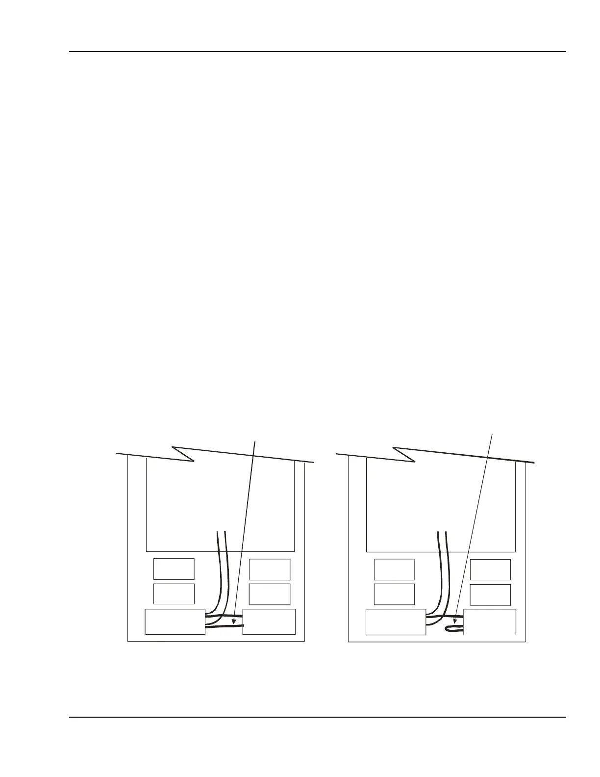
Refer to figure 2-11. In configuration “A”, (28 uF) two leads are connected to the lower right capacitor.
Thus, the capacitor is in-circuit in this configuration. Configuration “B” (15.5 uF) has one of the leads
removed from the terminals of this capacitor, thus the capacitor is out of the circuit.
• To change from configuration “A” to “B”, disconnect the interconnecting lower lead from the lower left
capacitor in figure 2-11, and connect it to the same terminal on the lower right. This removes the
lower right capacitor from the circuit.
• To change from configuration “B” to “A” in figure 2-11, reconnect the lead between the two capacitors,
as shown. This connects the capacitor into the circuit.
After the phase shift capacitors are correctly configured, set the DIP switches as follows:
• Locate the desired tube in table 2 of supplement 746026, which follows Chapter 2. With dual-speed
starter 901297-15 / 901298-15 set to configuration “A”, this starter is compatible with all tubes
requiring a 3 uF or 6 uF high-speed shift capacitor (unless indicated otherwise) and a 28, 30 or 31 uF
low-speed shift capacitor. When set to configuration “B”, it is only compatible with tubes requiring a 3
uF or 6 uF high-speed shift capacitor (unless indicated otherwise) and a 15.5 uF low-speed shift
capacitor.
• Note the DIP switch setting for the desired tube as per table 2.
• Set the DIP switches as per 2.8.2.
DUAL SPEED
STARTER
BOARD
CONFIGURATION “A”
CAPACITOR IN-CIRCUIT
(28 uF for TOSHIBA STATOR)
CONFIGURATION “B”
CAPACITOR OUT-OF-CIRCUIT
(15.5 uF for LOW-SPEED CGR STATOR)
CMP200_FIG2-11A.CDR
DUAL SPEED
STARTER
BOARD
Figure 2-11: Selection of phase shift capacitance
Use and disclosure is subject to the restrictions on the title page of this CPI document.
CMP 200
X-Ray Generator Service Manual Ch # 901476-02 Rev. P Page 2-27