Do you have a question about the Craftsman 139.53919D and is the answer not in the manual?
Explains safety symbols and signal words used in the manual to highlight potential hazards.
Lists the necessary hand tools required for assembly and installation of the garage door opener.
Details considerations for installing the opener on sectional garage doors, including reinforcement needs.
Provides installation guidelines for one-piece garage doors, noting reinforcement requirements and door bracket mounting.
Guides the user through assembling the garage door opener rail and installing the trolley.
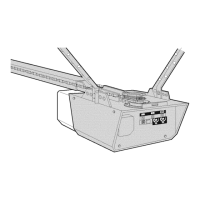
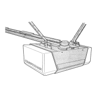
Instructs on securely attaching the assembled rail to the motor unit using the provided bracket and bolts.
Details the process of installing the idler pulley into the rail assembly for belt operation.
Explains how to install the drive belt onto the trolley and sprocket and secure the belt cap retainer.
Provides instructions on setting the optimal belt tension using the spring nut and trolley mechanism.
Explains how to determine and mark the correct location for the header bracket based on door type and travel.
Details the process for wall or ceiling mounting of the header bracket to structural supports.
Guides the user in connecting the rail assembly to the installed header bracket using a clevis pin.
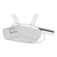
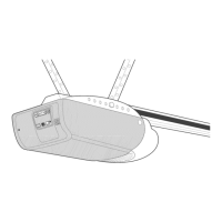
Provides instructions on positioning the opener unit relative to the garage door for optimal height and clearance.
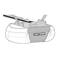
Details how to securely hang the opener unit from the garage ceiling or wall supports using hanging brackets.
Explains how to mount the wall-mounted door control and connect its wiring to the opener unit.
Guides the installation of light bulbs and lenses into the opener unit's end panel.
Details how to thread and attach the emergency release rope and handle to the trolley mechanism.
Outlines electrical requirements for the opener, including grounding and proper outlet connections.
Explains the installation and alignment of the safety reversing sensor system to ensure safe door operation.
Provides steps for mounting, wiring, and aligning the safety reversing sensors for proper operation.
Offers solutions for common issues with the safety reversing sensors, including indicator light problems.
Details how to attach the door bracket to sectional garage doors, including reinforcement requirements.
Guides the connection of the door arm sections to the trolley and door bracket for sectional doors.
Explains how to set the garage door opener's travel limits for opening and closing positions.
Details how to adjust the force required for the opener to open and close the garage door.
Provides instructions for testing the safety reversal system by verifying door reversal upon contact with an obstruction.
Guides the user in testing the Protector System (safety reversing sensor) functionality.
Details the functions and features of the motion detecting control console, including light and lock features.
Explains how to manually open the garage door by disconnecting the trolley using the emergency release handle.
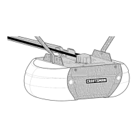
Provides instructions for mounting the battery backup unit directly on top of the motor unit.
Details how to mount the battery backup unit onto a ceiling structural support.
| Model Number | 139.53919D |
|---|---|
| Type | Chain Drive |
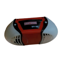
| Horsepower | 1/2 HP |
| Safety Sensors | Yes |
| Battery Backup | No |
| Drive System | Chain |
| Max Door Weight | 7 ft |
| Max Door Height | 7 ft (standard) |
| Voltage | 120V |