9
ENGLISH
Fig.R
31
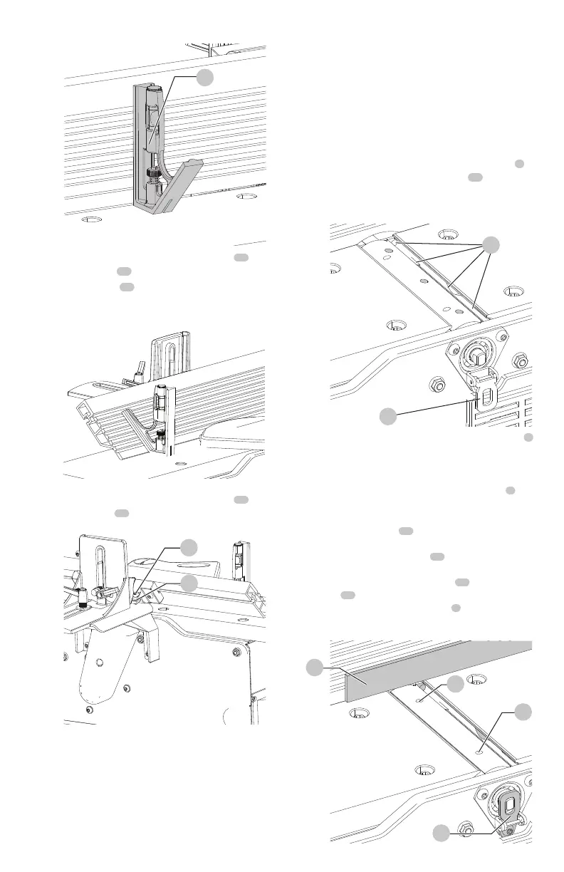
b. Using supplied hex wrench, turn set screw
29
until it
contacts stop
30
.
c. Using a square
31
, tilt the table to the 45° position
and make sure the fence is 45° to the table. Adjust
the fence ifnecessary.
Fig.S
d. Using supplied hex wrench, turn set screw
32
until it
contacts stop
33
.
Fig.T
32
33
e. These positive stops enable you to rapidly position
the table to the 90° and 45°settings.
CAUTION: Make sure the fence is in level contact with
the surface of the outfeedtable.
Adjusting Knives (Fig. U–Y)
WARNING: The knives aresharp.
WARNING: Disconnect machine from powersource.
WARNING: Be extremely careful that your hands do
not come in contact with theknives.
WARNING: Make certain that all knives are securely
fastened in cutterhead before turning onpower.
When it becomes necessary to replace or adjust the knives
due to replacement or wear:
1. Remove cutterheadguard.
2. To replace a knife, disengage the cutterhead lock
4
.
Rotate cutterhead, loosen four screws
34
and remove
bar and knife. Insert new knife and replace bar and
securely tighten four screws.
4
Fig.U
34
3. To adjust the knives, make sure the cutterhead lock
4
is not engaged. Make sure screws are not overly
tightened. Loosen each one half turn or only enough so
knife can slide between locking plate andcutterhead.
4. Rotate cutterhead and engage cutterhead lock
4
on
cutterhead shaft as shown. This will position knives for
proper adjustment to the outfeedtable.
5. Place a straight edge
37
on the outfeed table
extending out over the knife as shown. Using hex
wrench supplied, turn screw
35
until knife just touches
straight edge. Adjust knife at near end of cutterhead
in the same manner turning screw
36
. Tighten four
screws
34
after adjustment ismade.
NOTE: Make sure cutterhead lock
4
is disengaged after
adjustment is completed and replace cutterheadguard.
Fig.V
35
36
37
4
 Loading...