7
ENGLISH
OPERATION
WARNING: To reduce the risk of serious personal
injury, turn unit off and disconnect it from
power source before making any adjustments or
removing/installing attachments or accessories.
An accidental start-up can causeinjury.
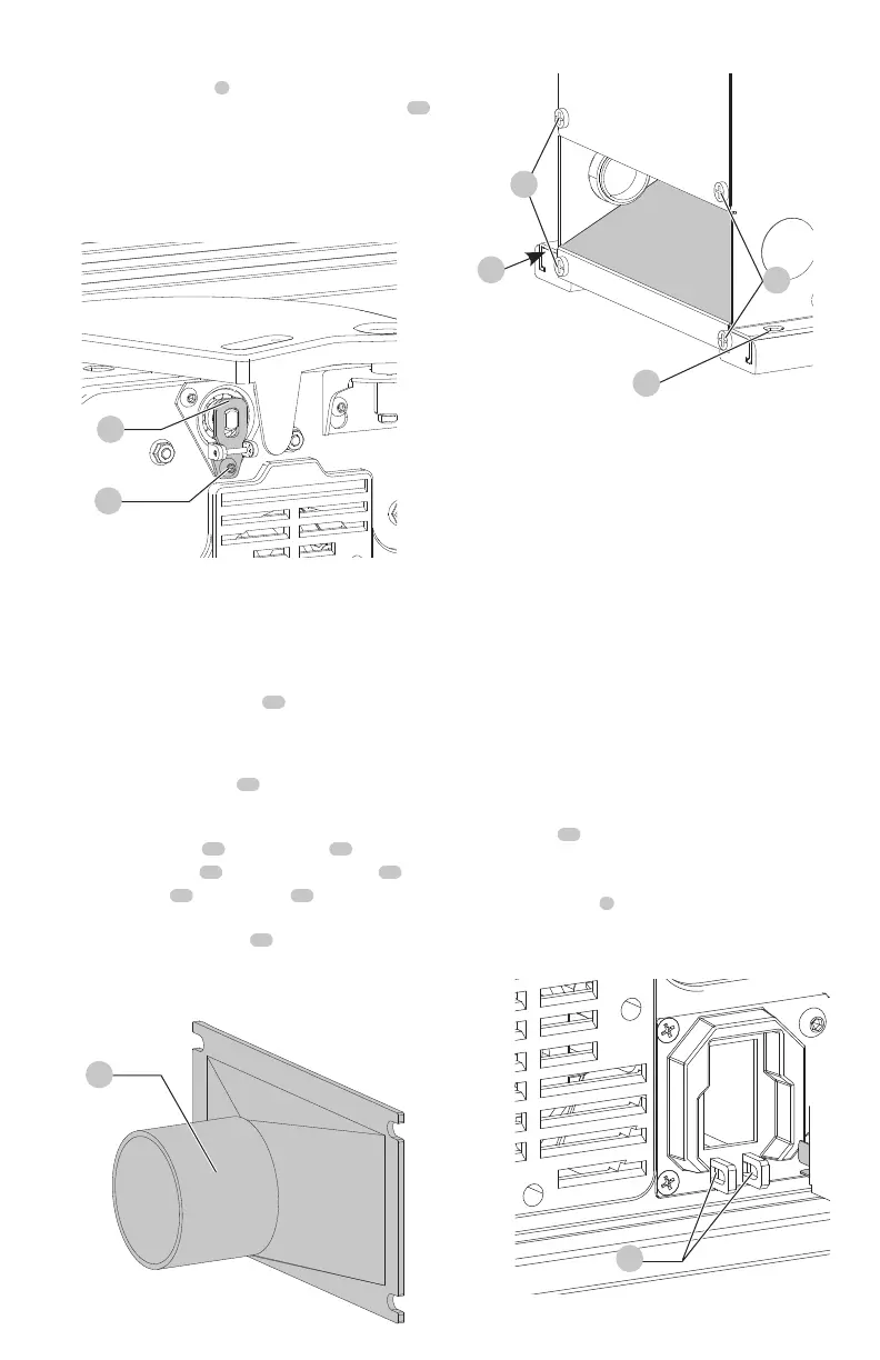
Cutterhead Lock (Fig. K2)
Assemble cutterhead lock
4
to the front side of the jointer
base, using the M6 x 1 mm x 12 mm button head screw
21
.
NOTE: The cutterhead lock is to be engaged with the
cutterhead shaft only when setting knives. All other
times, the cutterhead lock should be disengaged from
thecutterhead.
21
4
Fastening Jointer to Supporting Surface
(Fig. M)
If during operation, there is any tendency for the jointer
to tip over, slide or “walk” on the supporting surface, the
jointer must be secured to the supporting surface. Four
holes (two of which are shown at
22
Fig.M, are provided
for thispurpose.
Dust Collector Hose Adapter (Fig. L, M)
A dust collector hose adapter
23
is supplied with the
jointer to help connect it to a standard 2" (51 mm) vacuum
hose. To assemble the adapter:
1. Remove two screws
25
. Loosen screws
26
.
2. Slide adapter’s slots
24
under loosened screws
26
.
3. Tighten screws
26
when adapter
23
is in
properlocation.
4. Replace and tighten screws
25
.
NOTICE: Do not install this vacuum hose adapter
unless you will be using a dust collector.
Fig.L
23
Fig.K2
Stopping and Starting the Jointer
(Fig.A,N)
WARNING: Make sure that the switch is pressed
down so that the tool is turned "OFF" before
plugging in the power cord. In the event of a
power failure, press the switch down into the
"OFF" position. An accidental start-up can
causeinjury.
LOCKING THE SWITCH DOWN INTO THE "OFF" POSITION
NOTE: When the machine is not in use, the switch should
be locked in the down position to prevent unauthorized
use. Two holes
27
are provided in the bottom of the switch
housing (Fig. N) for locking off the planer with apadlock.
To turn the planer on:
1. Lift up the switch
5
(Fig. A). The planer locks on
automatically.
2. To turn the tool off, press the switch down.
Fig.N
27
Fig.M
25
26
22
22
 Loading...