53
Section 4.3: Testing Power Components
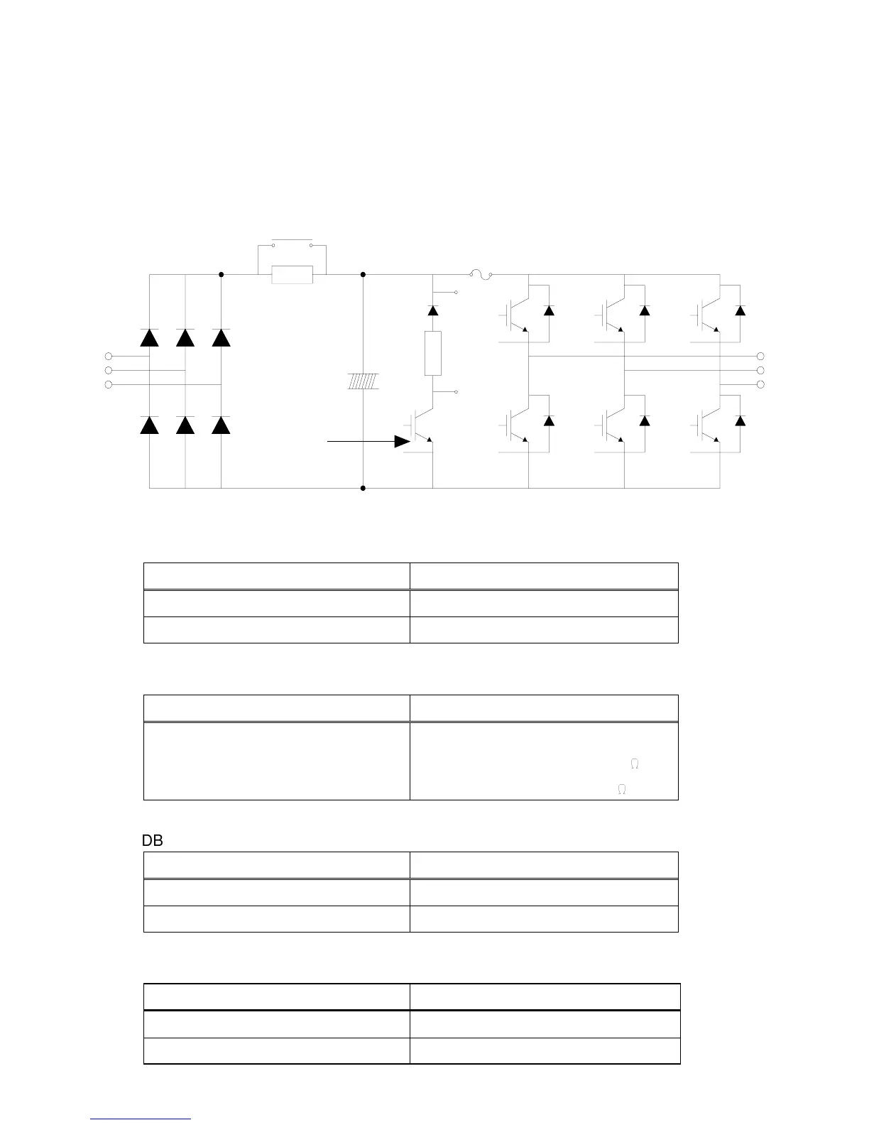
4.3.1 How to Check Power Components
Before checking the power components, be sure to disconnect the AC input supply and
wait until the main electrolytic capacitor (P1-N) discharges. This may take several minutes.
Fig. 4.3.1: SV100 Power Components Functional Diagram
Table 4.3.1: Power Component Test Values - All resistance values measured with multi-meter
leads From + to -.
Magnetic Contactor
R
S
T
U
V
W
P
N
B1
B2
Fuse for 460 VAC
models only
P1
G
E
GuP
EuP
GuN
EuN
GvP
GvN
GwP
GwN
EvP
EvN
EwP
EwN
Input Diode Module Check
Check Points
Resistance to be Good
From R, S, or T to P 50k ohms or more
From R, S, or T to N 50k ohms or more
Charge Resistor Check
Check Points
Resistance to be Good
From P to P1 Resistance depending on Models.
Models 446485-07/08 50
:
All other models 100
:
DB (Dynamic Braking) IGBT*
Check Points
Resistance to be Good
From B2 to N 50k ohms or more
From G to N A few kilo ohms
Output Diode Module Check
Check Points
Resistance to be Good
From U, V, or W to P1 and U, V, or W to N 50k ohms or more
Between Gate and Emitter of each IGBT A few kilo ohms
Electrolytic
Capacitors
Dynamic
Braking
IGBT*
Charge Resistor
*IGBT = Isolated Gate Bipolar Transistor