54
Section 4.4: Pushbutton Pendant Test
4.4.1 Interface Card Input and Output Test
The condition of the interface card can be monitored by using the 7-segment keypad
display. You must first go to Status of Input Terminal located in the User Level [Function
No.13 – InP]. Press the FUNC key and monitor the 7-segment display as you press the
respective pushbuttons. B4 is an dry contact output used for brake control and indicates
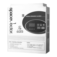
when the drive has activated the brake release. Example: If F and 3 terminals are
energized, Figure 4.4.1 shows the lights are ON for those respective terminals. R, B4, P
and 2 indicator lights are lit in the OFF row signifying that they are not energized.
Fig. 4.4.1: LED display for interface card test.
• Each column represents an input terminal of your interface card.
4.4.2 Control Board Input and Output Test
The condition of the input terminals and brake control output can be monitored by using
the 7-segment keypad display. Remove the interface card. Go to Status of Input Terminal
located in the User Level [Function No.13 – InP]. Press the FUNC key and monitor the
7-segment display as you close the connection between the respective inputs and CM on
the main control board. The inputs are sinking type DC inputs, so using a jumper wire
between the input and CM should cause the input to be on. MO is an open collector
output used for brake control and indicates when the drive has activated the brake release.
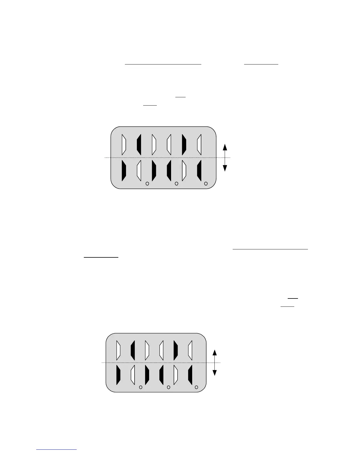
Example: If FX and P3 terminals are jumpered, Figure 4.4.2 shows the lights are ON for
those respective terminals. RX, MO, P3 and P1 indicator lights are lit in the OFF row
signifying that they are not energized.
Fig. 4.4.2: LED display for Control Board Input test.
ON
OFF
R F B4 P 3 2
ON
OFF
RX FX MO P3 P2 P1