7
Through these openings, it is possible to see an underlying
insert which is red when the valve is open and yellow
when the valve is closed.
If the valve is not completely open, a mixed red/yellow colour
can be seen. In compliance with UNI EN 250 standard, it takes
more than two complete turns of the handwheel to shift from a
closed to a completely open position.
A Ø 3 mm metal hose at the base of the valve prevents any
impurity, condensation liquids or water from entering valves at
the end of the hose so that also when swimming downwards or
with the head lower than the legs the air will still flow from the
cylinder to the regulator.
ASSEMBLY
Before assembling the scuba, make sure that the cylinder (or the
cylinders) is pressurized only with compressed air at the nominal
working pressure, in compliance with the breathable air provi-
sions set forth in the UNI EN 12021 standard.
Please note that only the cylinders provided with a cumulative test
certificate (in compliance with PED 97/23/CE Directive) can be
pressurized within the time period specified in the above certificate.
In Europe, the cumulative test certificate (in compliance with
PED 97/23/CE Directive) has a 4-year validity for new cylinders,
and a 2-year validity after each following successful test.
ASSEMBLY OF BUOYANCY COMPENSATOR
AND BACK-PACK
Connect the jacket or the back-pack to the cylinder (or cylin-
ders). The back-pack features straps to hold the scuba
equipment.
On fastening the back-pack to the cylinder make sure that the
valve air outlet in the proper position for connection with the air
regulator. It is better to keep the upper side of the back-pack 3
to 4 cm below the valve air outlet, so that neither the valve nor
the cylinder foot will hamper the diver when swimming.
NOTE
The cylinder must be safely secured with the straps to prevent it
from slipping away while diving. Make sure the straps have been
inserted in the proper sequence into the locking buckle. Holding
the cylinder by the back-pack, shake it several to make sure the
two parts hold together.
ASSEMBLY OF THE REGULATOR
After securing the jacket or the back-pack with the straps the
assembly of the regulator can begin.
NOTE
Check the valve o-ring for cuts or deterioration. It must be
replaced every 3 months, even if in perfect condition, because it
is exposed to high pressure from the cylinder and to weather
conditions.
Only original Cressi-sub spare parts have to be used.
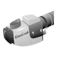
Remove yoke screw and dust cap. Make sure the II Stage is on
the correct side before placing the I Stage against the air outlet
of the valve.
Put yoke screw into place to attach I Stage to the valve. It is not
necessary to overtighten.
Turn the tap anticlockwise keeping the II Stage air flow button
pressed. As soon as the air starts flowing out of the II Stage
release the button and open the tap completely. Through the
loop-holes at the base of the tap you should see a red tape now.
It is advisable to turn the tap clockwise by a fraction of a turn in
order not to damage the thread of the stem.
In case of a second independent regulator connect it to the
additional outlet of the valve following the above instructions.
Connect the BC low pressure hose with the power inflator
placed at the end of the corrugated hose.
TESTING
Check cylinder pressure with the underwater pressure gauge or
with a computer with pressure gauge function. Pressure must
be 200 bar.
Rubinetteria 27-09-2005 15:09 Pagina 7
 Loading...