Crestron C2ENET-1/-2 2-Series Ethernet Interface Expansion Cards
address is 192.168.1.0, then an error message will be generated. Refer to the “e-
Control Hardware Configuration” section within the latest version of the Crestron
e-Control
®
Reference Guide (Doc. 6052) for more information.
For Dynamic IP Addressing
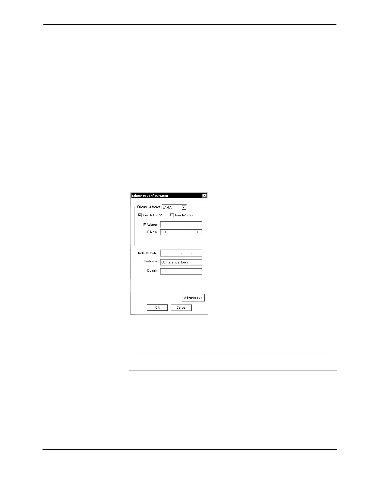
1. Select the Enable DHCP check box to enable DHCP with a Windows
2000/3000 Server; for a Windows NT 4.0 Server, select both the Enable
DHCP and the Enable WINS check boxes. The IP Address and IP Mask
fields will be ignored if either check box is selected. (Refer to VT Pro-e on-
line help for more information on DHCP settings.)
2. Enter the hostname of the control system in the Hostname field. The
hostname identifies the machine on the network and is automatically
translated into the numerical IP address. The hostname can consist of up to
64 characters. Valid characters are 0 – 9, A – Z (not case sensitive), and the
dash (hyphen character). No other characters are valid. The hostname
cannot begin with a dash or number.
3. The IP address of the default router is provided by the DHCP server and
thus the Default Router field should be left blank.
“Ethernet Configuration” Window
If applicable, enter the domain in the Domain field. This is necessary only if you are
configuring DHCP on an Ethernet connection to a control system that currently has a
static address. The domain name will be used to reconnect to the control system after
it reboots. With a serial connection, the domain does not need to be entered.
NOTE: The domain supplied by the DHCP server will overwrite the domain that is
indicated in this field.
Advanced Settings (optional):
1. Click the Advanced button to set optional parameters. (Refer to the figure
on the next page.) You can enter the IP address of the primary DNS server
in the DNS Server 1 field; enter the IP address of the secondary DNS Server
in field 2.
Operations & Installation Guide – DOC. 5962B 2-Series Ethernet Interface Expansion Cards: C2ENET-1 & C2ENET-2 • 9