Product Manual — Doc. 9195A CEN-GW1 and CENI-GW1 • 8
Controls and Indicators
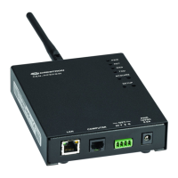
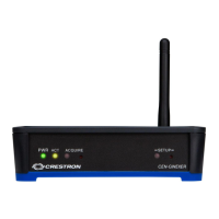
PWR (1) Bi-color green/amber LED;
Green indicates operating power is being supplied via PoE or 24VDC;
Amber indicates that the device is booting
ACT EX/ER (1) Green LED;
Indicates infiNETEXand ER wireless RX and TX data activity
ACT SG (1) Green LED;
Indicates SG wireless RX and TX data activity
ACQUIRE (1) Recessed pushbutton with red LED:
Used to enter Acquire mode to pair wireless devices;
Press to enter and exit Acquire mode
SETUP (1) Recessed pushbutton with red LED
Used to set up connection with the control system via Ethernet;
To factory reset the gateway, press and hold SETUP until the SETUP LED flashes
6times.
RESET (1) Recessed pushbutton;
To reboot the gateway, press and hold RESET for 8 seconds.
LAN PoE (1) Green and (1) Amber LED;
Green indicates Ethernet link status;
Amber indicates Ethernet activity
Connectors
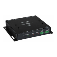
ANTENNA EX/ER (1) Connection for supplied EX/ER antenna or antenna extender
ANTENNA SG (1) Connection for supplied SG antenna or antenna extender;
CEN-GW1: Yellow bands around the top;
CENI-GW1: Gray bands around the top
COMPUTER (1) Micro-B USB female;
Computer console port, installer use only;
For setup and firmware upgrades
G (1) 4-40 screw, chassis ground lug
24VDC 0.75A (1) 2.1 x 5.5 mm DC power connector;
24VDC power input;
PW-2407WU power pack sold separately
LAN PoE (1) 8-pin RJ-45, female;
10BASE-T/100BASE-TX Ethernet port;
Power over Ethernet compliant

 Loading...