Crestron DIN-DALI-2 DIN Rail 2 Channel DALI Interface
Programming Guide – DOC. 7365A DIN Rail 2 Channel DALI Interface: DIN-DALI-2
9
⇒ 1 – 4: Intermediate values indicate some form of problem.
NOTE: The values should not be read immediately after powering up the
system as ballasts may not have been polled five times yet.
• LISTBALCFG [LOOP] ALL COMMISSIONED
The COMMISSIONED flag is 0 or 1.
⇒ 1: The ballast was commissioned and the DIN-DALI-2 expects to see it
on the loop. If the ballast is not physically present, the DIN-DALI-2
reports it as missing and tries to replace the address during the ballast
replacement process.
⇒ 0: The ballast was not commissioned as is not expected to be on the
loop. If there is a ballast found at that address, the DIN-DALI-2 reports
it as new and tries to assign it an address for a missing ballast if one
exists.
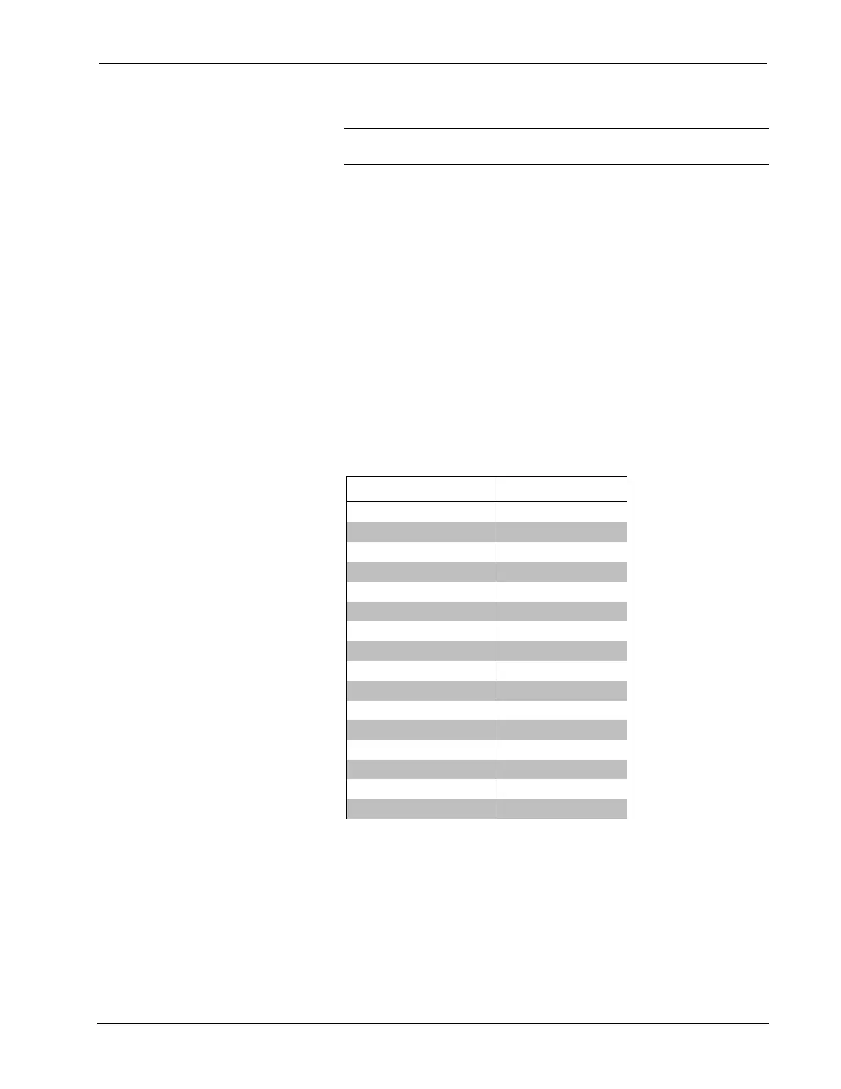
• LISTBALCFG [LOOP] ALL FADETIME
ALL FADETIME displays the fade time used when scenes are recalled or
intensity commands (analogs) are sent. The fade time is mapped into real
time as shown in the following table.
Ballast Settings and Fade Times
BALLAST SETTING FADE TIME
0 <0.7 s
1 0.7 s
2 1 s
3 1.4 s
4 2 s
5 2.8 s (Default)
6 4 s
7 5.6 s
8 8 s
9 11.3 s
10 16 s
11 22.6 s
12 32 s
13 45.2 s
14 64 s
15 90.5 s
• LISTBALCFG [LOOP] ALL FADERATE
ALL FADERATE displays the fade rate used when raise/lower commands
(digitals) are sent. The fade rate is mapped into steps/second as shown in
the table on the following page.
 Loading...