DigitalMedia 8G+™ Receiver 200 Crestron DM-RMC-200-C
Connectors, Controls & Indicators (Continued)
#
CONNECTORS
1
,
CONTROLS &
INDICATORS
DESCRIPTION
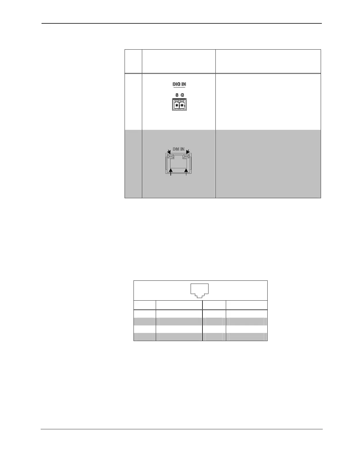
19
DIG IN
(1) 2-pin 3.5 mm detachable terminal
block;
Digital/contact closure sensing input;
Rated for 0-24 Volts DC, referenced
to GND;
Input Impedance: 2.2k Ohms pulled up to
5 Volts DC;
Logic Threshold: 2.5 Volts DC nominal
with 1 Volt hysteresis band
20
DM IN
6
AMBER
LED
GREEN
LED
PIN 1
PIN 8
(1) 8-pin RJ-45 female, shielded, with
two LED indicators;
DM 8G+ input;
Connects to DM 8G+ output of a DM
switcher, transmitter, or other DM device
via CAT5e or Crestron DM-CBL-8G
cable
7
;
Green LED indicates DM link status;
Solid amber LED indicates HDCP video;
Blinking amber LED indicates non-HDCP
video
1. Interface connectors for the AUDIO OUT (Speaker), DIG IN, COM, IR, and RELAY ports are
provided with the unit.
2. The set of speaker-level audio outputs on the top panel and the set of speaker-level audio outputs on
the rear panel cannot be used simultaneously. Either set of speaker-level audio outputs should be used
at one time.
3. To determine which is pin 1 on the cable, hold the cable so that the end of the eight pin modular plug
is facing away from you, with the clip down and copper side up. Pin 1 is on the far left.
4. HDMI requires an appropriate adapter or interface cable to accommodate a DVI signal.
CBL-HD-DVI interface cable sold separately.
5. Maximum string length for serial commands sent via the IR port should be no greater than
40 characters.
6. The DM IN port consists of one RJ-45 connector. Refer to the following table for the
connector pinouts.
DM IN Connector Pinouts
18
PIN # WIRE COLOR PIN # WIRE COLOR
1 Orange/White 5 Blue/White
2 Orange 6 Green
3 Green/White 7 Brown/White
4 Blue 8 Brown
7. For DM 8G+ wiring up to 330 feet (100 meters) between devices, use Crestron DM-CBL-8G
DigitalMedia 8G cable, Crestron DM-CBL DigitalMedia cable, Crestron DM-CBL-D DigitalMedia D
cable, or generic CAT5e (or better) UTP or STP. Shielded cable and connectors are recommended to
safeguard against unpredictable environmental electrical noise which may impact performance at
resolutions above 1080p. Refer to the latest version of the Crestron DigitalMedia Infrastructure Guide
(Doc. 4556) for complete wiring guidelines and to the Crestron DigitalMedia Design Guide (Doc.
4789) for complete system design guidelines. All cable sold separately.
16 • DigitalMedia 8G+™ Receiver 200: DM-RMC-200-C Operations & Installation Guide – DOC. 7126B
 Loading...