Crestron FT-TS600 FlipTop Touch Screen
Operations & Installation Guide – DOC. 7585B FlipTop Touch Screen: FT-TS600 • 11
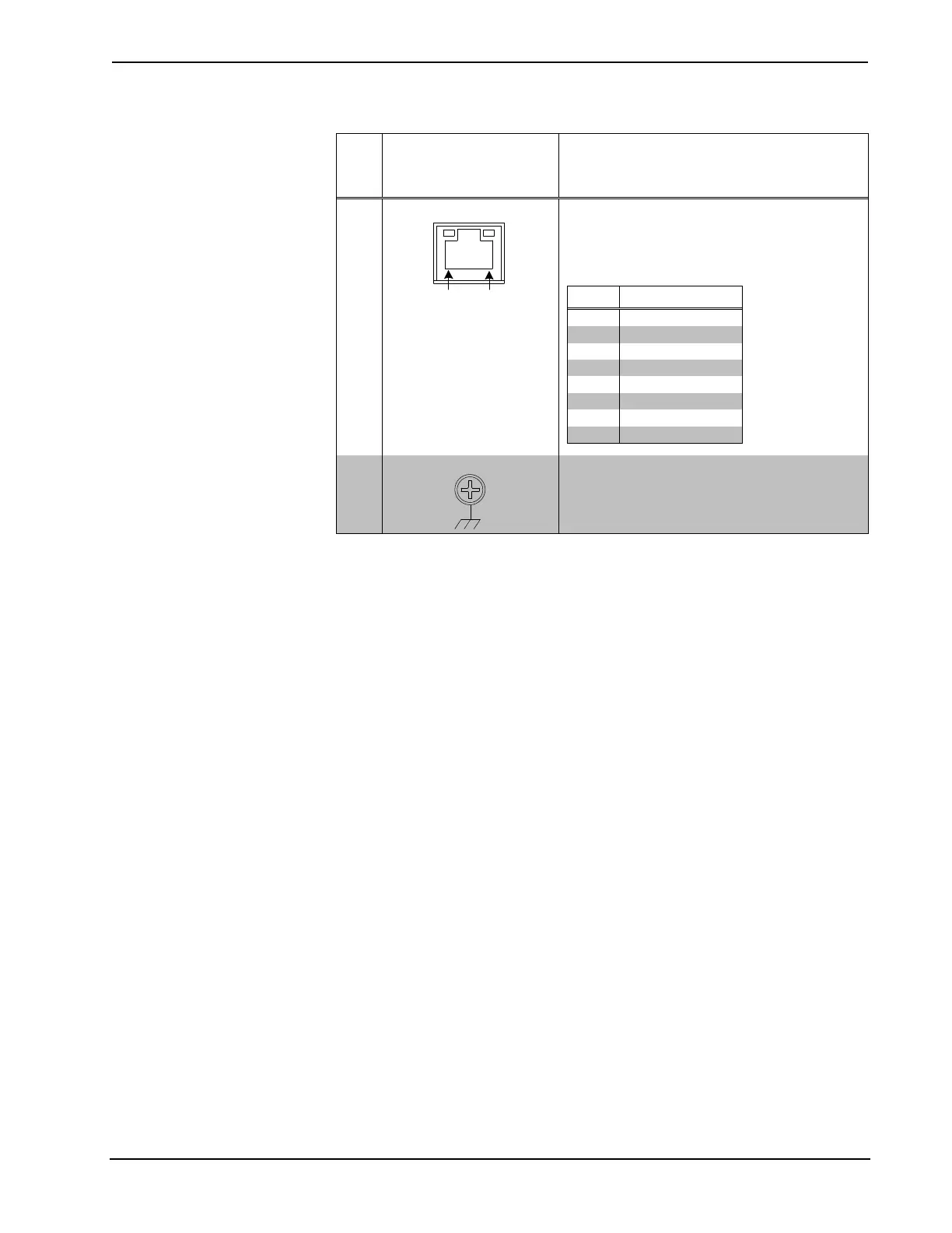
Connectors, Controls, and Indicators (Continued)
# CONNECTORS
1
,
CONTROLS, AND
INDICATORS
DESCRIPTION
5 LAN PoE
(1) 8-pin RJ-45 with two LED indicators;
10BASE-T/100BASE-TX Ethernet port;
Power over Ethernet compliant;
Green LED indicates link status;
Yellow LED indicates Ethernet activity
6 G (Ground)
(1) 6-32 screw, chassis ground lug
1. An interface connector for the AUD OUT port is provided with the unit.
2. PoE+ dc power can also be available on a TX/RX pair.
 Loading...