Crestron AV3 & PRO3 3-Series Control Systems
Operations Guide – DOC. 7330C 3-Series Control Systems: AV3 & PRO3
15
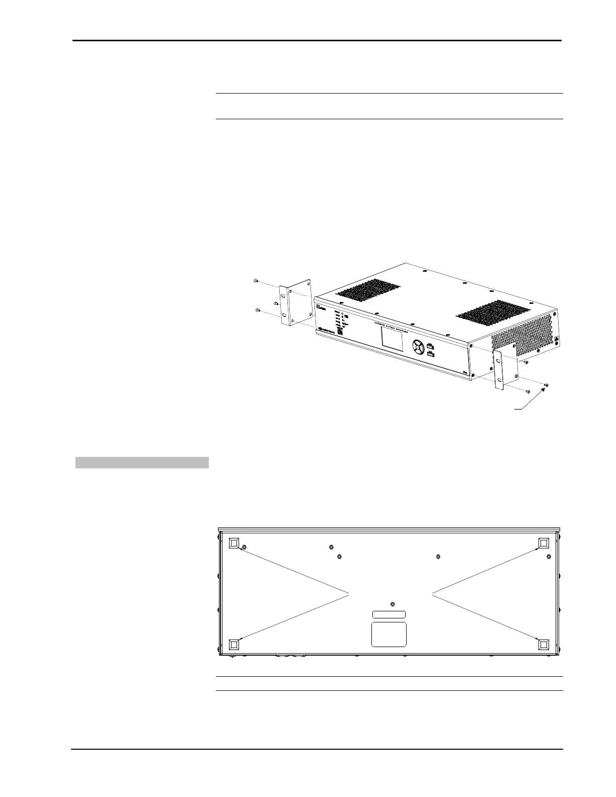
To install the ears, use the following procedure.
CAUTION: To prevent equipment damage, use only the rack ears Crestron
provides for this device.
1. There are screws that secure each side of the AV3 and PRO3 top cover.
Using a #1 or #2 Phillips screwdriver, remove the three screws closest to
the front panel from one side of the unit. Refer to the diagram following
step 3 for a detailed view.
2. Position a rack ear so that its mounting holes align with the holes vacated
by the screws in step 1.
3. Secure the ear to the unit with three screws from step 1, as shown in the
diagram that follows.
Ear Attachment for Rack Mounting
4. Repeat procedure (steps 1 through 3) to attach the remaining ear to the
opposite side.
Stacking
Four “feet” are provided with the AV3 and PRO3 so that if the unit is not rack
mounted, the rubber feet can provide stability when the unit is placed on a flat
surface or stacked. These feet should be attached prior to the hookup procedure.
Refer to the following illustration for placement of the feet.
Foot Placement for the AV3 & PRO3
NOTE: No more than two AV3 or PRO3 units should be stacked.