3-Series Control Systems Crestron AV3 & PRO3
16
3-Series Control Systems: AV3 & PRO3 Operations Guide – DOC. 7330C
Hardware Hookup
Connect the Device
Make the necessary connections as called out in the illustrations that follow this
paragraph. Apply power after all connections have been made.
When making connections to the AV3 and PRO3, note the following:
• Use Crestron power supplies for Crestron equipment.
• The included cables cannot be extended.
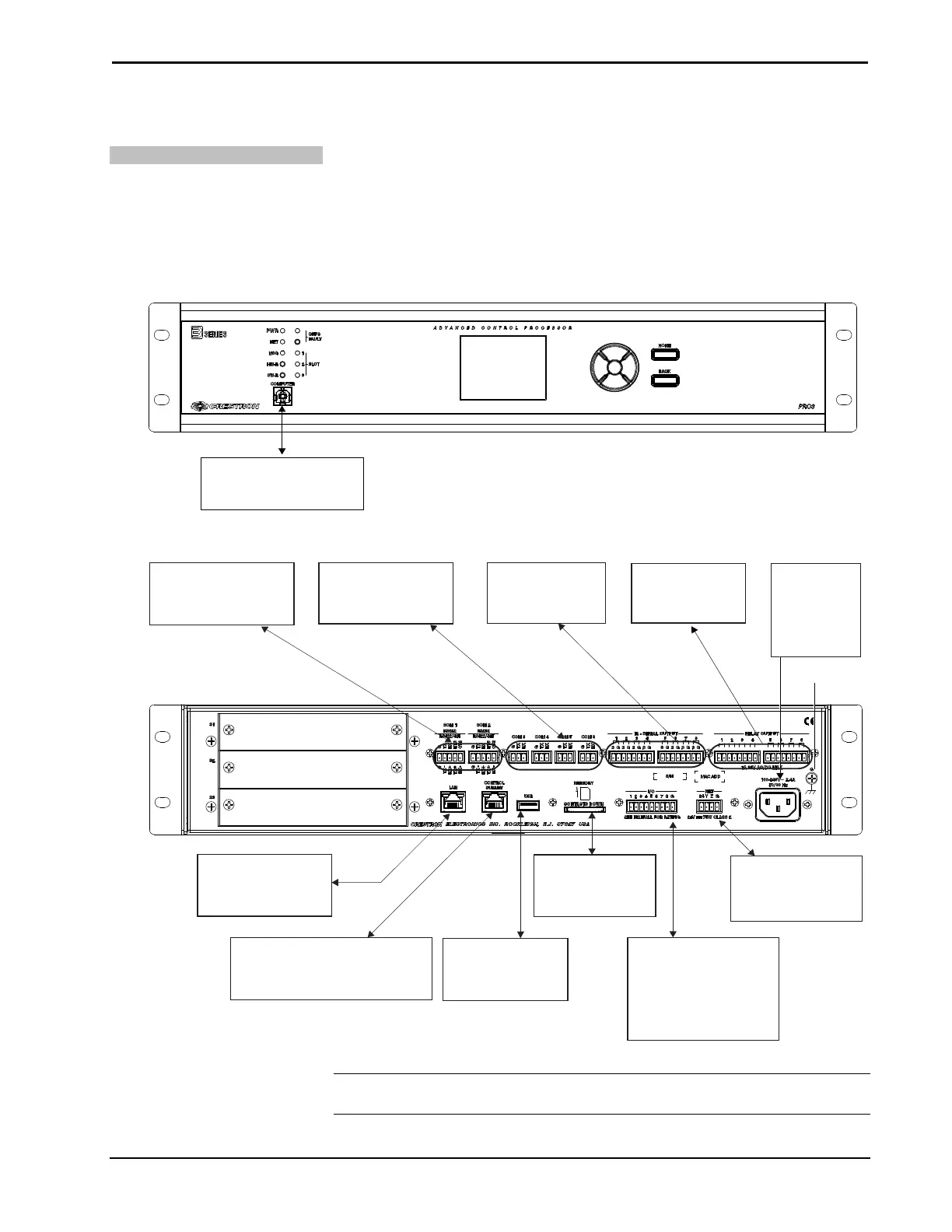
Hardware Connections for the AV3 & PRO3 (Front Panel)
COMPUTER:
To Computer Console
Hardware Connections for the AV3 & PRO3 (Rear Panel)
Relay (1 - 8):
To Controllable
Devices
IR-Serial (1 - 8):
To IRP2 or
Serial Devices
COM (3 - 6):
To RS-232 Devices
COM (1 - 2):
To RS-232/422/485
Devices
100-240V
~2.4A
50/60Hz:
Main Power
Input
Ground
MEMORY:
To Multimedia
Memory Card
NET (24 Y Z G):
To Any Cresnet
Network Device
I/O 1 - 8:
To Controllable Devices
From Device Outputs
- Contact Closures
- Relay Closures
USB:
To USB Mass
Storage Device
LAN:
10/100/1000 BASE-T
Ethernet to LAN
CONTROL SUBNET:
10/100/1000 BASE-T
Ethernet to Crestron Devices
NOTE: Ensure the unit is properly grounded by connecting the chassis ground lug
to an earth ground (building steel).