Do you have a question about the CrimeStopper RS900/RS901 and is the answer not in the manual?
Controls programming, valet mode, and starter disable functionality.
Serves as a Valet/Programming indicator and security deterrent.
Connects to the vehicle's parking light circuit for output.
Connects to the vehicle's horn trigger wire for chirp/honk function.
Connects to the vehicle chassis metal for a proper ground connection.
Programmable output for Ignition or Anti-Grind/Starter Disable functions.
Provides a ground pulse for factory electric trunk release or accessories.
Triggers remote start from a host alarm or factory keyless entry system.
Connects to hood pin switch to inhibit remote start if hood is open.
Input for diesel glow plug indicator for timed remote start.
Disables remote start when the brake pedal is depressed.
Provides ground pulse to disarm factory anti-theft systems before remote start.
Provides ground pulse to rearm factory anti-theft systems after remote start.
Input for engine RPM sensing in Tach Reference mode.
Defines the Green, Red, and Blue wire functions for door lock control.
Recommends identifying the vehicle's locking system before connecting wires.
Lists common vehicle makes and their typical door lock trigger polarity.
Lists optional accessories for door lock systems.
Explains jumper pins used to configure IGN2/ACC2 and Parking Light outputs.
Procedure to adjust voltage reference level to lower engine cranking time.
Assists in locating a valid tach source by flashing parking lights.
Procedure to program the unit to recognize the tach signal.
Procedure for learning up to 4 different transmitter codes for the system.
Steps to use one remote to control a second vehicle with an identical system.
General procedure to access and change programmable features.
Programs tach signal from Red/White wire when button 2 is pressed.
Controls automatic door locking/unlocking with ignition status.
Sets duration (0.75 or 3 sec.) for lock/unlock pulses.
Sends two unlock pulses for interfacing with other systems.
Controls Green wire input selection for aftermarket/factory keyless entry.
Enables automatic Anti-Grind output 1 min after ignition off.
Adds optional 3 short chirps when requesting a remote start.
Controls automatic locking during/after remote start abort or time-out.
Adjust voltage reference for Smart Tachless mode to reduce crank time.
Configures Yellow/Black wire as Negative IGN or Anti-Grind output.
Sets engine run time for remote start (12, 24, 36, or 48 min).
Resets all programmable options to their default positions.
Controls the unit's multi-function output, defaulting to Negative IGN.
Determines the engine run duration for remote start.
Resets all options to default settings.
Indicates unit is in Valet mode; requires specific button sequence to exit.
Indicates a fault at the Brake or Hood sensor; check installation and sensors.
May be due to factory anti-theft systems or multiple ignition circuits.
Often caused by missing secondary ignition circuits for onboard systems.
Check power/ground connections and antenna module connection.
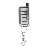
| Number of Buttons on Remotes | 5 |
|---|---|
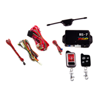
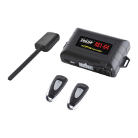
| Number of Remotes | 2 |
| LED Status Indicator | Yes |
| Valet Mode | Yes |
| Turbo Timer | No |
| Remote Trunk Release | Yes |
| Type | Remote Starter |
| Features | Remote start, keyless entry |
| Remote Start Confirmation | Yes |
| Engine Start | Yes |