Operation Crowcon Gasmaster
18
2
PPB
PPM
0
0
V/V
0
0
LEL
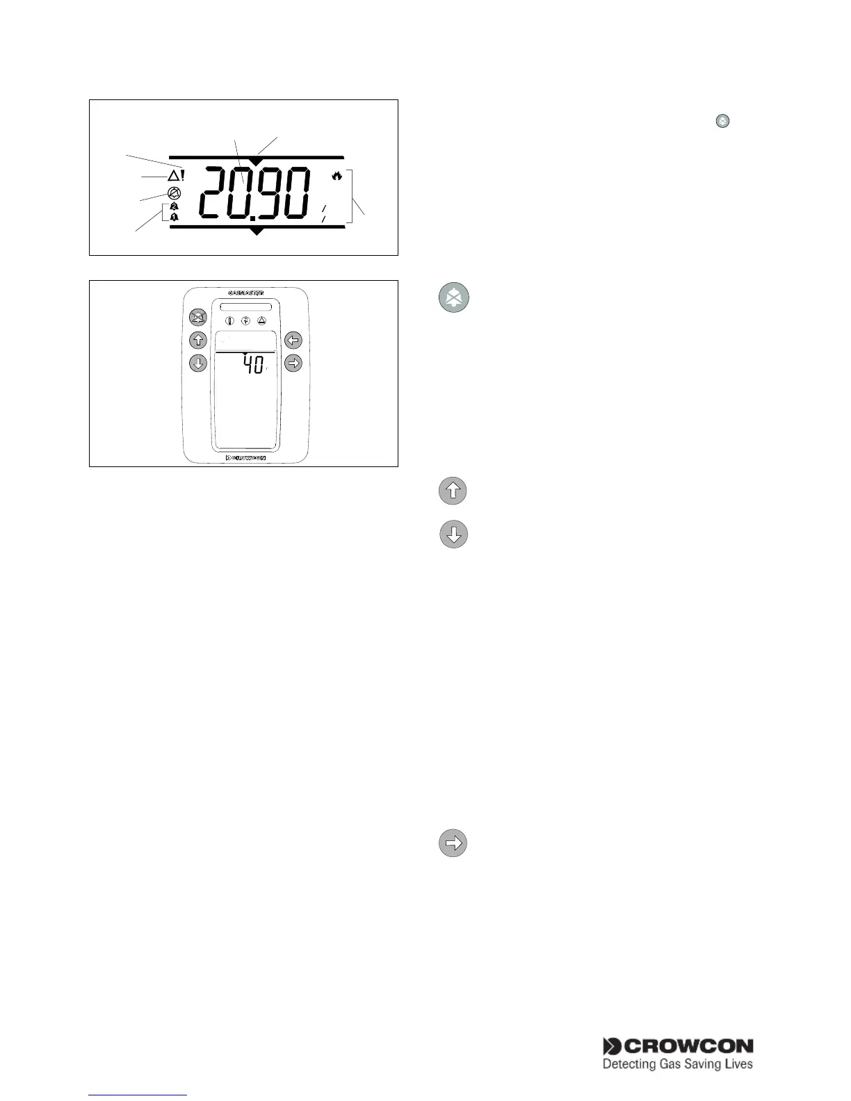
Units
Channel
number
Gas
reading
Alarms
Channel
Inhibit
Warning
Fault
Figure 3.2
0
0
#1=CH4
1
4
LEL
User display Gasmaster 1
Display panel LEDs
The LEDs on the Gasmaster Display Panel
indicate the following:
Yellow Fault LED:
Lights when any detector or system fault
is detected (see page 24 for a list of fault
messages). The fault LED operates with the
common fault relay, and can be set as latched
or non-latched dependant on the system con-
figuration.
Yellow Warning LED:
Lights when a warning condition is present
(see page 26 for a list of warning messages).
The warning LED will automatically reset
when the cause is cleared.
Green Power LED:
Is normally on when power is present, and
will switch off briefly once every five seconds
to indicate that the system is operational. The
LED will flash on and off every second when
Gasmaster is operating from its batteries due
to power failure.
Red Alarm Bar:
Will flash when an alarm from any channel is
triggered, and will remain in a steady 'on'
state when the accept/reset button
is
pressed. The LED bar will flash again if a new
alarm is triggered.
Operator Panel Buttons
Use the five operator buttons to respond to alarm
conditions, examine the status of system settings,
and configure Gasmaster.
ACCEPT/RESET
Press the Accept/Reset button to mute
the internal sounder and external alarms.
When alarm or fault conditions have
cleared, press Accept/Reset again to
reset the system.
Double-click the Accept/Reset button
to exit the menu system and return to
message display.
UP and DOWN
Use the Up and Down buttons to scroll
through menu items.
Press and hold the Up or Down button
to move quickly through the menu items.
Double-click the Up or Down button to
move directly to the top or bottom of
the alpha-numeric characters when con-
figuring text or entering the Supervisor
password
In Supervisor Mode (see section 3.7),
use the Up and Down buttons to change
values or settings.
In normal, non-alarm conditions, press and
hold the Up and Down buttons to adjust
the message display area brightness.
CONTINUE
Use the Continue button to display avail-
able menus. The menu system can be
accessed during normal channel monitor-
ing, alarm or fault condition. Gasmaster
has four standard menus plus one
advanced menu. See figure 3.5 on page
25 for an overview of Gasmaster’s Menu
System. The standard and advanced
menus are as follows: