Crowcon Gasmaster Installation
7
2.8 Connecting input devices
Gasmaster may be fitted with between one and
four input modules (one only for Gasmaster 1) of
the following types:
•4-20mA/Fire module for 4-20mA type
detectors, conventional smoke/heat detec-
tors or ESU.
•mVPellistormoduleformVbridgetypeflam-
mable gas detectors.
Details of hardware configurations and link set-
tings can be found in section 2.8.1 to 2.8.6.
4-20 mA Inputs
Gasmaster provides analogue 4-20 mA inputs
with a sensor supply voltage of 19 to 28 V dc and
measures the signal across a 98 Ω sense resistor.
Inputs can be gas detectors or flame detectors
in 4-20 mA 2-wire sink, or 3-wire sink or source
configurations. Gasmaster will track inputs from
3 to 21.5 mA at which point an 'over-range' fault
will be indicated. Connection details are shown in
section 2.8.1 and 2.8.2.
Conventional fire detectors
A loop of up to 20 conventional smoke/heat
detectors (for example Apollo Series 65 or Orbis
+
+
+
+
+
+
Pb
CROWCON
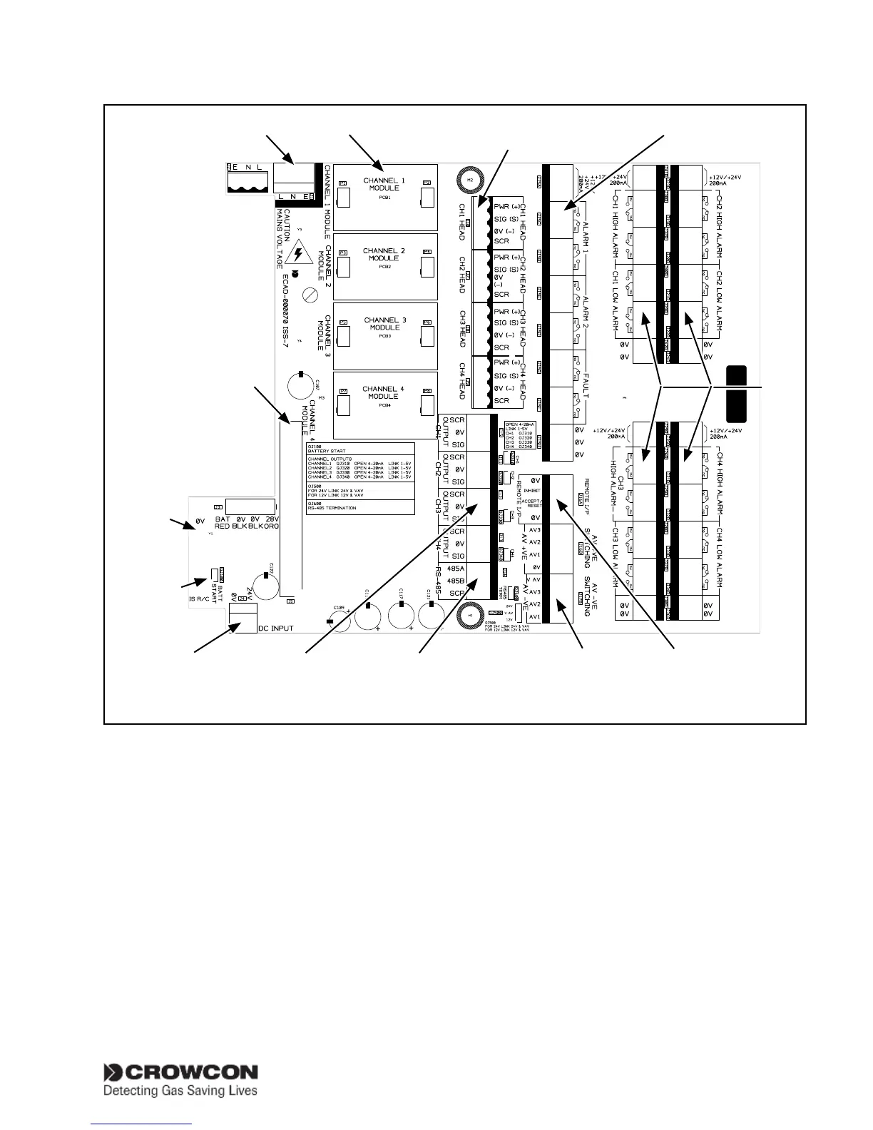
Figure 2.5 Terminal PCB layout
Mains supply Input modules Common relay terminals
Channel
relay
terminals
Remote inhibit and
accept/reset inputs
RS-485 Modbus terminals
Audible/Visual
Alarm terminals
Analogue
outputs
24 V dc supply.
Link to chassis
on I.S. systems
only.
Link to chassis
on non-I.S.
systems only.
Display PCB
connector
Detector input
terminals