Crowcon Gasmaster Installation
11
Warning
Crowcon strongly recommends that remote
inhibit switches be key operated only, and that
access to the key should be restricted to author-
ised personnel. A Gasmaster system that has
been inhibited without other safety precautions
being in place may not provide the protection
for which it was designed. Steps should be
taken to ensure that all appropriate personnel
are aware when a Gasmaster system is inhibited.
Remote ACCEPT/RESET
Close the contact momentarily to accept alarms
and cancel audible alarms. Close the contact
again when the hazard is cleared to reset alarms.
Remote INHIBIT
Closing the contact will inhibit alarms on all input
channels. Channels will remain inhibited until
the contact is opened; the Gasmaster will then
return to its original state (any channels that have
been set to inhibit using the Supervisor menu
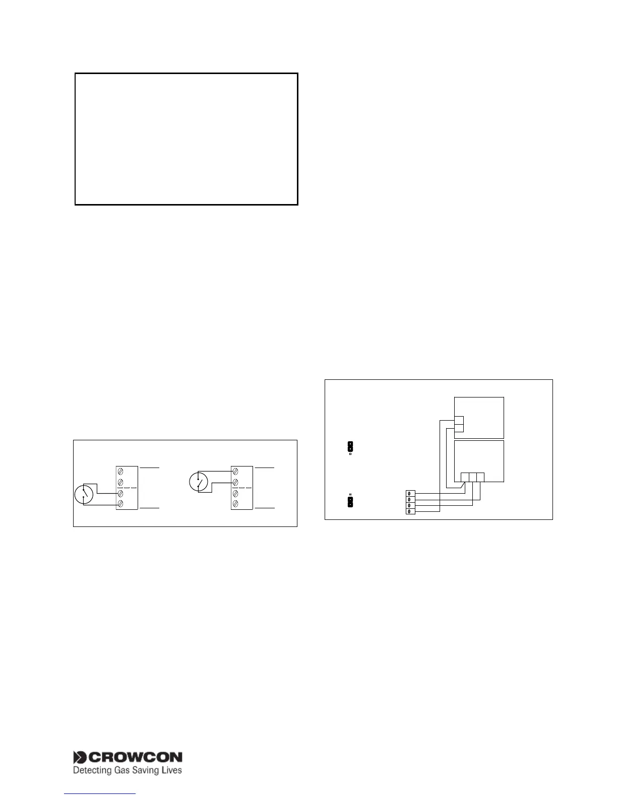
will remain inhibited). Figure 2.15 shows wiring
configurations for remote inputs.
Crowcon recommends screened cables for con-
necting remote switches. The screen should be
terminated at the appropriate ‘SCR’ terminal.
Figure 2.15
0V
INHIBIT
ACCEPT/
RESET
0V
REMOTE
I/P
0V
INHIBIT
ACCEPT/
RESET
0V
REMOTE I/P
Remote Accept/Reset Global Inhibit
Connections for remote inhibit/accept/reset
inputs
2.9 Connecting output devices
WARNING: After accounting for internal power
consumption, the maximum power available for
input and output devices is 48 W
2.9.1. Audible visual alarms
Figure 2.16 shows a typical wiring diagram for
audible & visual (A/V) alarms, in this example a
two-tone sounder is depicted. The A/V drive from
Gasmaster is capable of providing up to 650mA,
which equates to two general purpose A/V alarm
devices using xenon type beacons. A greater
number of LED-based beacons may be powered;
contact Crowcon for advice.
Gasmaster is compatible with 12 V dc or 24 V
dc A/V alarms (Gasmaster can be set for 12v or
24V output; not both): refer to Figure 2.16 for
link settings.
Gasmaster is compatible with A/V alarms which
require a common 0V supply (+VE switched), or
a common +VE DC supply (0V or ‘-VE’ switched).
Connect the A/V device to the ‘AV +VE SWITCHING’
or ‘AV -VE SWITCHING’ terminals as appropriate.
Two separate sounder outputs are provided to
activate on level 1 and level 2 alarms respectively
(terminal AV2 becomes active on alarm level 1;
AV3 becomes active on alarm level 2). If a single
tone sounder is used, connections should be to
terminal AV2 (and the common terminal) only.
The sounder will activate on alarm level 1.
Terminal AV1 is intended to drive a visual alarm
and activates on a level 1 alarm.
Figure 2.16
+
-
V S2S1
SOUNDER
BEACON
AV3
AV2
AV1
AV -ve
AUDIBLE VISUAL
ALARM 1
Loop all connections to
a second audible visual
alarm if required.
for 12V Alarm Devices
12V
VAV
24V
12V
VAV
24V
for 24V Alarm Devices
Link Settings
Link Settings
VAV
CONNECTIONS FOR A
0V (-VE) SWITCHED
A/V DEVICE
Connections for AV drive
2.9.2. Common relay connections
Double-Pole-Change-Over (DPCO) relays with
contact rating of 250 V ac 8 A (non-inductive),
5 A (inductive) are provided for Alarm 1, Alarm 2
and Fault. Each relay can be set in its non-active
state as energised (Fail safe) or de-energised. It is
common practice to set the Fault relay as Fail Safe
so in the event of power loss, the fault relay will
change state. See Figure 2.5 for Common Relay
terminal location and Figure 2.17 for contact
definitions. Terminals are fitted adjacent to all
relay blocks to provide 12 V or 24 V dc supplies
for switching low power devices. The dc auxiliary