Installation Crowcon Gasmaster
10
the sensor is set to minimum and avoid potentially
burning-out the pellistor by applying excessive
voltage.
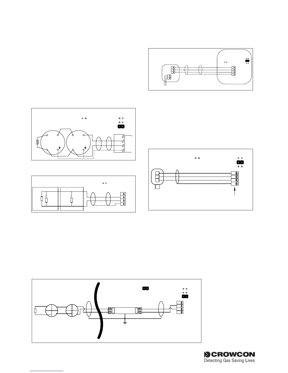
2.8.4. Heat/smoke detectors
Conventional fire detectors for safe area use
should be setup according to Figures 2.10 and
2.11. Conventional fire detectors for hazardous
area use should be setup according to Figure 2.12.
Figure 2.11 shows connections for manual alarm
call points.
Figure 2.10
PWR
SIG
0V
SCR
Smoke/Heat
detector
L2
COM-
IN+
L2
1K8
Channel Link Settings
FIRE
SINK
SOURCE
I.S. Link Settings
COM-
IN+
Connections for smoke/heat detector,
4-20mA/Fire input module
Figure 2.11
Manual alarm call points
1K8
470R 470R
0V
SIG
PWR
SCR
I.S. Link Settings
Connections for manual alarm call points,
4-20mA/Fire input module
2.8.5. Environmental Sampling Unit
(ESU)
Figure 2.13 shows the wiring configuration for
monitoring the ESU sampling device. Gas detec-
tors fitted to the ESU should be cabled separately
to the appropriate input channels on the
Gasmaster or other control panel. For connec-
tions, details are shown on the instructions pro-
vided with the ESU.
Figure 2.13
Gasmaster
ESU SAMPLING DEVICE TERMINAL BOX
To Fan
0V
SIG
PWR
SCR
Channel Link Settings
FIRE
SINK
SOURCE
-
+
SIG
FAN-
FAN+
Input
1,2,3
or 4
I.S. Link Settings
Connections for ESU sampling device,
4-20mA/Fire input module
2.8.6. Flame detectors
Figure 2.14 shows a typical wiring configuration
for a 4-20 mA 3 wire Flame detector. Set the
detector type link appropriate for the type of
flame detector, refer to Figure 2.5. Do not set
link to FIRE.
Figure 2.14
0V
SIG
PWR
SCR
S
-
DETECTOR
Channel Link Settings
FIRE
SINK
SOURCE
Gasmaster
Detector Input
Terminals
+
I.S. Link Settings
Connections for 4-20 mA 3 wire Flame
detector, 4-20mA/Fire input module
2.8.7. Remote inhibit and accept/
reset inputs
Gasmaster has inputs for the connection of
remote switches to inhibit alarm outputs or
accept and reset alarms. Inputs are activated
when pulled down to 0 V, the open circuit volt-
age is 5 V dc.