I.S. Link Settings
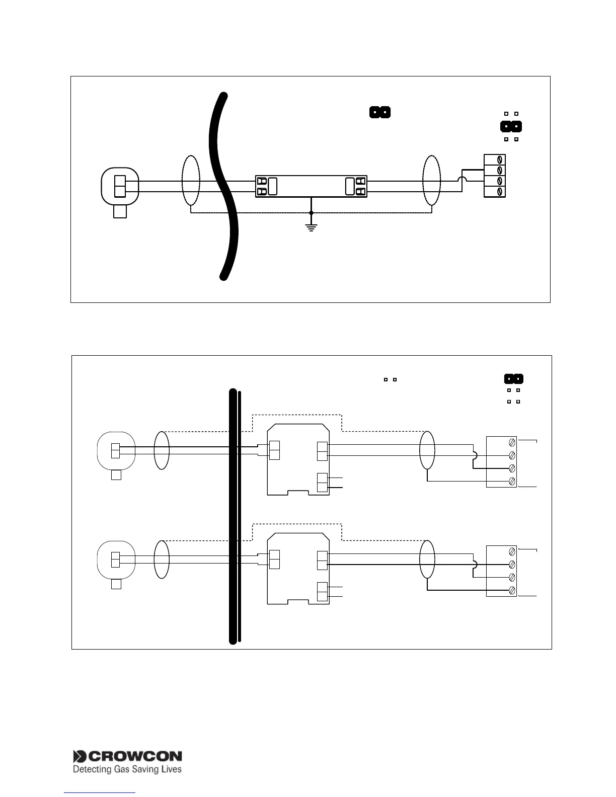
Figure 2.7 Typical connections for 2 wire I.S. detector with Zener barrier, 4-20mA/Fire input module Set channel link
to SINK (see figure 2.5) and configuration to DET4-20 SINK (see Menu System Overview section, page 25 and 33.
Refer to earth connection requirements on Figure 2.5, page 7
SAFE
AREA
HAZARDOUS
AREA
0V
SIG
SCR
PWR
+
–
+
–
Detector
Detector
MTL
5541
Pepper
l&
Fuchs
KFD2-STC4-Ex1.H
1
2
1
1
12
13
14
–
+
20-35Vd
c
suppl
y
3
1
7
8
15
1
4
–
+
20-35Vd
c
suppl
y
0V
SIG
SCR
PWR
Channel Link Settings
FIRE
SINK
SOURCE
I.S. Link Settings
Figure 2.8 Typical connections for 2 wire I.S. detector with Galvanic Isolator, 4-20mA/Fire input module. Set channel
link to SRCE (see figure 2.5) and configuration to DET4-20 SRCE (see Menu System Overview section, page 25 and 33.