Installation Crowcon Gasmaster
8
devices’) can be connected to each Gasmaster
input channel. A fire loop can also comprise
switched devices such as manual alarm call points
or flame detectors, and devices can be mixed
on the same loop provided electrical character-
istics are compatible and fire regulations allow.
Switched devices require a 470 Ω series resistor.
Each fire loop must be terminated with a 1K8
end-of-line resistor, which is monitored to provide
indication of open circuit or short circuit faults.
Connection details are shown in section 2.8.3.
Environmental Sampling Unit (ESU)
Each Gasmaster input can monitor a Crowcon
Environmental Sampling Unit (ESU), which ena-
bles detection of flammable or toxic gases over
a wide area using a sample draw technique. It
is essential that the sampling device on the ESU
is operating correctly, and Gasmaster provides
this monitoring function to ensure a sample is
being drawn. Gasmaster provides a 2-wire 24
V dc supply to the sampling device. Separate
Gasmaster input channels are required to monitor
the gas detector or detectors fitted to the ESU.
Connection details are shown in section 2.8.5.
mV bridge pellistor detectors
Some flammable gas detectors provide a mV
bridge type signal rather than a 4-20mA signal.
Example Crowcon products are Xgard Type 3 and
Xgard Type 4. The procedure for setting-up these
detectors is different from 4-20mA devices: refer
to section 2.12.1 for detailed instructions on com-
missioning mV bridge type detectors
Please contact Crowcon for specific wiring
details for Crowcon detectors
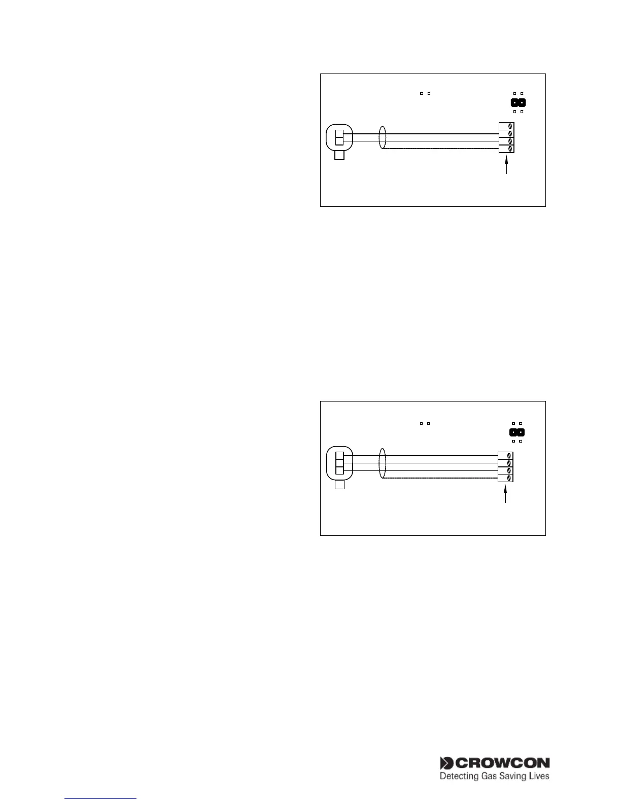
2.8.1. Two wire 4-20mA devices
Figure 2.6 shows a typical wiring configuration
for a 2-wire current sink detector for safe area
use only.
Figures 2.7 and 2.8 show typical wiring configura-
tions for I.S. detectors installed in hazardous areas
using Zener Barriers or Galvanic isolators. Refer
also to section 1.3.
Set the link on the 4-20 mA/Fire input module to
SINK in all cases.
Figure 2.6
0V
SIG
PWR
SCR
+
-
DETECTOR
Channel Link Settings
FIRE
SINK
SOURCE
Gasmaster
Detector Input
Terminals
I.S. Link Settings
Connections for 2 wire detector 4-20mA/Fire
input module
Figures 2.7 and 2.8 show typical wiring configura-
tions for a 2 wire sink I.S.detector with Zener
barrier or Galvanic Isolator. Set the link for the
appropriate channel as shown in each diagram.
2.8.2. Three wire 4-20mA devices
Figure 2.9 shows a typical wiring configuration
for a 3-wire detector. Set the link on the 4-20 mA/
Fire input module to SOURCE for a current source
detector, and SINK for a detector configured as
current sink.
Figure 2.9
0V
SIG
PWR
SCR
S
-
DETECTOR
Channel Link Settings
FIRE
SINK
SOURCE
Gasmaster
Detector Input
Terminals
+
I.S. Link Settings
Connections for 3 wire detector 4-20mA/Fire
input module
2.8.3. mV bridge pellistor detectors.
Detectors such as Crowcon’s Xgard Type 3 or 4
should be connected as shown. Refer to section
2.12.1 for instructions on detector set-up.
Refer to Figure 5.1 on page 37 for wiring details.
Warning: Ensure the ‘Head Voltage’ potentiom-
eter is set fully anti-clockwise before connecting
and powering mV pellistor type detectors for the
first time (or when fitting a new/replacement mV
module). This will ensure the voltage supplied to