Crowcon Gasmaster Menu system overview
31
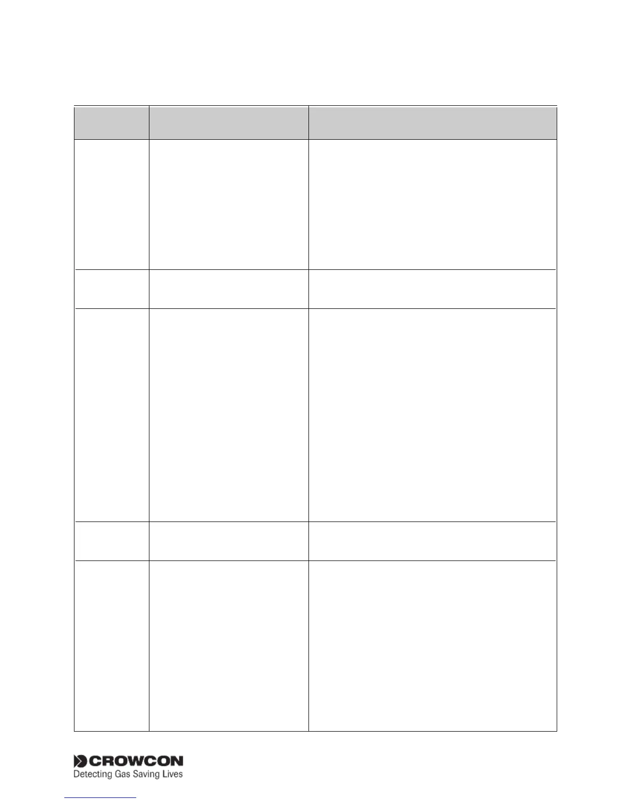
Relay alarm L1
Values = No alarm
In alarm
Relay alarm L2
Values = No alarm
In alarm
Configure Select from config sub menus
Use to change below
system settings
System ModBus addr
Values = 1 to 254
Serial comms
Values = 9600, 8, N, 1
9600, 8, N, 2
Identity
Values = 16 character
string
Mains Fail
Values = AS WARNING Determines whether a main supply fail is treated as a
AS FAULT fault or a warning
Language Language The default display language is English. A second
Values = English (UK) language may be available depending on system
configurable configuration.
AV drive Beacon type Determines the operation of beacons connected to
Values = Latched the 'AV1 Drive' terminal.
Non-latched Latched means that in an alarm state, the beacon will
continue flashing when the Accept/Reset button is
pressed, and will only stop flashing when the alarm is
cleared and the Accept/Reset button is pressed again.
Non-latched means that the beacon will continue
flashing when the Accept/Reset button is pressed, but
stop automatically when non-latching alarms have
reset.
Sounder type Determines the operation of sounders connected to
Values = Latched the 'AV2/3 Drive' terminals.
Non-latched Latched means that in an alarm state, the sounder
Menu Item Values (as shown on display) Description
Supervisor menu (allows system tests to be performed, and configurations to be changed. A pass
cont. word is required to enter this mode, see section 3.7 for details.)
Forces level 1, 2 relays for the selected channel.
The channel warning symbol
will show.
Contact orientation will depend on whether the relay
is configured as normally energised or de-energised.
Press Back to exit, the relay will return to its normal
state.
Required for RS-485 digital communications only,
any address in the range can be chosen. If multiple
units are connected on an addressable loop to a
'Master' controller, each Gasmaster must have a dif-
ferent address.
Describes the required RS-485 communications
parameters; Gasmaster is factory set to 2 stop bit.
Allows a system name to be entered which will be
shown on the Gasmaster display when the appropri-
ate mode is selected (see section 3.4). Use the Up
and Down buttons to enter required alpha-numeric
characters and press Continue to accept.
No alarms will be activated on Gasmaster. Use to test
remote displays.
Press Back to exit, the input will return to its normal
state.