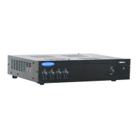
Commercial Audio Series Mixer-Amplifiers
page 10
Operation Manual
2.5 Wire Your System
Typical input and output wiring is shown in Figure 2.7
INPUTS: Connect microphones or balanced line-level
sources to mixer-amplifier balanced inputs. Set Mic/Line
switches accordingly. Connect unbalanced line-level sig-
nals to RCA input connectors.
OUTPUTS: Maintain proper polarity (+/–) on output con-
nectors.
For each amplifier channel, connect the Amplifier Output
screw terminals to the loudspeaker loads. Use terminals
marked COM and 4 OHMS for a 4-ohm loudspeaker load,
or use terminals marked COM and 70V or 100V for con-
stant-voltage loudspeaker loads.
Connect the COM terminal to speaker negative (–) lead;
connect one of the other terminals to speaker positive (+)
lead.
For more application drawings, see the enclosed
Commercial Audio Mixer-Amplifier Quick-Start Guide.
NOTE: Crown provides a reference of wiring pin assign-
ments for commonly used connector types in the Crown
Amplifier Application Guide available at www.crownaudio.
2 Setup
Figure 2.7 Input and Output Wiring
Satellite Receiver
Dual Drive CD
DVD / VCR
1-VCAP
LM-201
LM-301A
Ceiling Speakers
PZM-11LLWR
CD