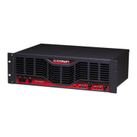
CE Series Service Manual
Rev. D
Turn off the amplifier and set up the DMM to measure
the voltage at U105-7. Turn on the amplifier and ob-
serve this voltage. Before the relays click in, U105-7
should be positive, and after they click in U105-7 should
be negative. If this is not the case, suspect R179, and
U105.
For every condition that J5 presents an open circuit,
the “fault” LED should blink, with one exception; when
the amplifier is off, the LED cannot blink. Verify that
when the amplifier is in its turn-on delay, the “fault”
LEDs both blink. If they don’t, but the fault jack oper-
ates correctly, suspect D124, C122, R180, R182, R183,
E102, E181, and R105.
At the completion of testing, set all switches per cus-
tomer request. If none are specified by the customer,
the following are standard factory settings for original
shipment:
Mode Switch: STEREO position.
Input Sensitivity Switch: To 1.4V position.
Level Controls: Both down (counter-clockwise) fully.
Type of Test Input Signal and Comments
or Adjustment Load Parameters
15. Fault Jack No Signal
No Load
Post Testing Procedure
Maintenance 2-9

 Loading...