CE Series Service Manual
Rev. D
Field Modifications 9-5
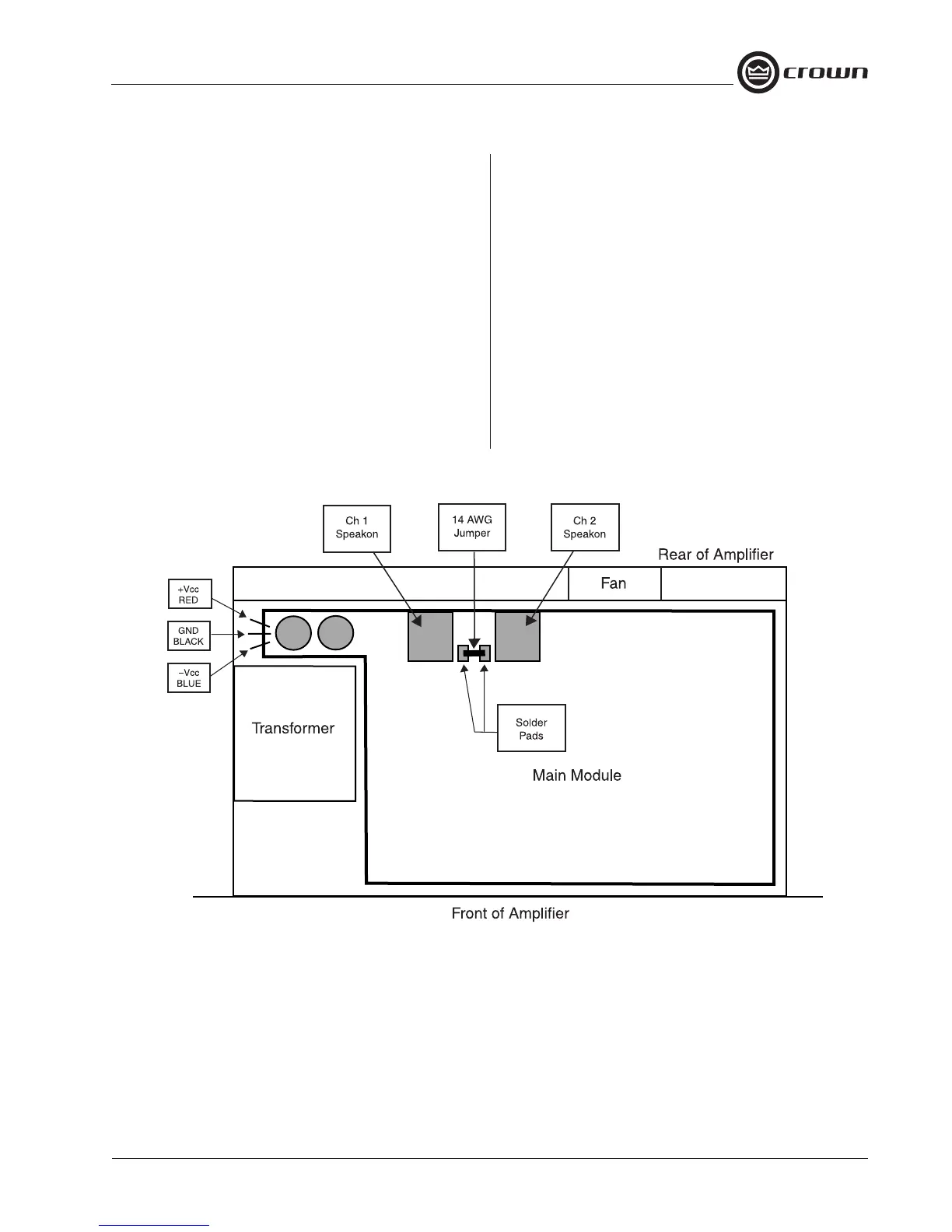
9.5 Channel 1 Output to Channel 2
Speakon Modification
Applicability: CE-1000, CE-2000, UT-1010, UT-2020,
S2, S3, M-120 and M-240 amplifiers.
Purpose of Modification: By default, the Channel 1
Speakon connector has Channel 1 signal present on
Pins 1+ and 1-, and Channel 2 signal present on Pins
2+ and 2–. The Channel 2 Speakon connector has
Channel 2 signal present on Pins 1+ and 1–. Perform
this modification to allow Channel 1 output signal to
be present on Pins 2+ and 2– on the Channel 2
Speakon connector. Amplifiers come from the factory
without this jumper installed, so normally Channel 1
output is not available from the Channel 2 Speakon.
Procedure:
1. Solder a 14 AWG wire across the two solder pads
indicated in Figure 9.7 below. This will route the Chan-
nel 1 output signal to the Channel 2 Speakon.
Caution: Before performing this modification, be sure
that:
• Amplifier power is turned off and AC cord un-
plugged.
• All input and output connectors have been removed.
• Supply capacitors have been discharged as per
the procedure detailed in Section 2.2 Cautions and
Warnings, page 2-1.
• Because this amplifier contains surface mount com-
ponents, all ESD safety precautions should be fol-
lowed.
Figure 9.7 Channel 2 Speakon Jumper