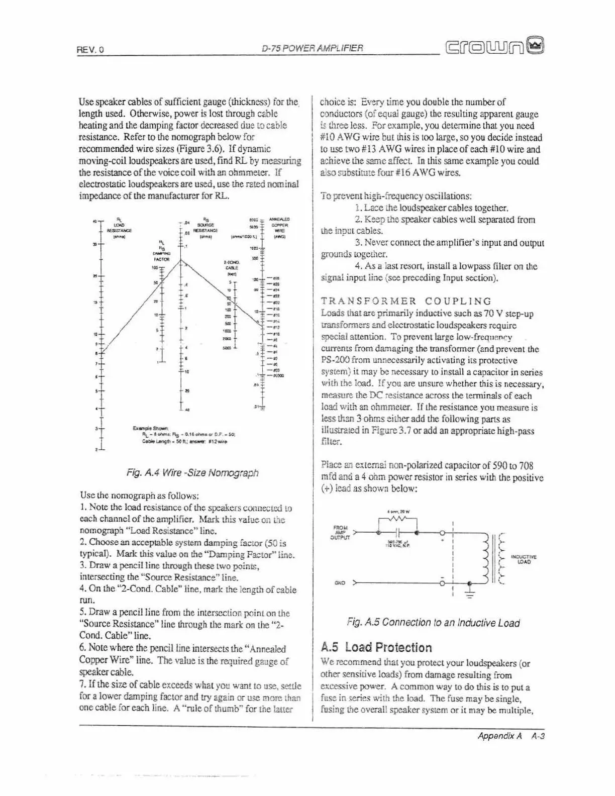
Use speaker
ca
bles
of
sufficie
nt
gauge
(th
icknes
s)
fo;
the
.
leng
th
used. Otherwise, power
is
lost through cable
heating a
nd
th
e damping factor decreased due
lO
cable
resis
tan
ce. Refer
to
!he
nomograph below for
recommcnded wire sizes
~'F
i
g
ur
e
3.6). If dynamic
mov
in
g-co
ill
oudspcakers are used,
find
RL
by
mezsuring
th
e resis
tan
ce
of
the
voice coil
with
en
ohmmeter. If
electrostatic loudspeakers
arc
used, use
th
e rated n
om
inal
impedance
of
the manufacturer
for
RL.
•
,
"
~
-,~
-
-
-t
_.
--
.--
--:
.::
- -
0
,
•
-
"
~
.-
-
-
•
-
T-
o
•
;f
-~
o
_
~
•
-m
•
•
I
•
--
r
~I
--
':1
-"1-
.',
-.-
r
-
..
•
-
...
:1
-.
'1
r
r
.. -
..
-.
•
-.
I:
--
.
--
I
"I
.J
._-
'\_
........
'"
·o.,,_
..
o .•
_~
c......,
..
.
loCO":
_ ·
,,!-.
F
ig.
AA
Wire
·Size
Nomograph
Use
lhc
no
mograph
as
follows:
I.
Note
th
e l
oad
resistance of
!he
speakers connecrcd
to
each channel
of
the
amplifier.
f\1ark
th
is
value
on
the
nomograph "Load Resistancc" line.
2. Choose
an
acceptable system
dam
p
in
g
fa=EOr
(50
is
t
yp
ical).
Mar
k this value
on
th
e "Damping Factor"li."e.
3.
Draw a penci
lli
nc
through these
two
points,
intersec
ti
ng
th
e "Source Resistance" line.
4.
On the "2-Con
d.
Cable'"1ine, mark
the
length
of
cable
run.
5.
Draw a
penc
il
line
from
the intersection point
on
the
"Sou
rce
Resis
tan
ce"line through the mark
on
the "2-
Con
do
Cable" l
in
e.
6.
Note where
the
pe
ncil
line
intersects the "Annealed
Copper
Wi
r
e"
line. The val
ue
is
the required gauge of
speaker cable.
7.
If
the
size of cable exceeds
whGt
yOt!
wa'lt
to
U
~,
se:tJe
ror
a lower damping
fac
to
r
and
try again or
use
more
man
on
e cable for each line. A "rule of thumb"
for
the
Lalter
choice
is:
Every
ti
me
you
double the number of
c'::ln
ductors (of equal gaug
e)
the
re
s
ulti
ng
ap
pare
nt
gauge
is
three less.
Fo
r
ex
ample.
you
detennine that
yo
u need
ilO
A
WO
wire but this is
tOO
large, so
yo
u decide instead
to
use
two #13 A
WG
wires in place of each #10 wire
an
d
ao:
h.
ieve the same affect.
in
th
is
same example
you
co
uld
also
subs
ti
tute four#16
AWG
wires.
To prevent high-
freq
uen
cy oscillations:
1.
La~e
the
lo
udspeaker cables togeth
er.
2.
K~ep
lhe s
peak
er cables well separated
from
!.he
input cab
les.
3.
Ne
ve
rconncct
the
amplifier's i
npu
t a
nd
ou
tp
ut
grounds
mgc!.her.
4.
As
a jast resort,
in
sta
ll
a lowpass filter
on
th
e
sig
na
l
in
polline (sec preceding Input
sec
ti
on).
TRAN
SF
ORME
R
COUPLING
Loads
that
a...-e
primarily
ind
uc
ti
ve
su
ch
as
70
V step-up
transformers
and elec
tro
static loudspeakers require
special attention. To prevent large
10w-frcqur,[lCY
currem.s
from
d
a/rla
ging the uansformcr
(a
nd
pr
evcnt
the
PS
-200 f
r:>m
unnecessari
ly
activating its protective
system)
it
may
be
necessary
LO
insta
ll
a capacitor in series
with
Ll:le
ioa
d.
If
yo
u
are
un
su
re
whether
th
is
is
necessary,
measure
the
DC resista
nc
e across
the
tenninals
of
each
load.
with
an
ohmmeter. If
the
re
sistance
you
measure is
less
th:m
3 o
hrr.
s either
add
the fo
ll
owi
ng
parts
as
illustr2.ted
in
Figure
3.7
or add
an
appropriate high-pass
filter.
Place
an
e:>;{emai
no
n-polarized capacitor of 590
to
708
mfd
an
d a 4
ohm
power resistor
in
series w
ilh
the positive
(+) iead
as
shown
be
low:
..L
=
Fig. A.5
Connection
to
an
Inductive Load
A.
S Load Protection
We
recomme
nd
thal
you
protec
l your loudspeakers
(o
r
other sensi
ti
ve
loads) from damage resulting from
excessive power. A co
mmon
way
to
do
!h
is is
to
put a
fuse
in series wim!.he
load.
The fu
se
rna)'
be
single,
fUSing
Lite
overa
ll
speaker
sys
tem
or
it
may
be
mUl
tiple,
Ap
pendix A A·3