Do you have a question about the Crown Geodyne II and is the answer not in the manual?
Provides an overview of the Geodyne II amplifier and its service manual.
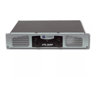
Describes the Geodyne II as a compact, professional audio power amplifier.
Details warranty policies and customer service contact information.
Outlines steps for effective troubleshooting and repair procedures.
Guide on how to identify and diagnose amplifier issues and faults.
Step-by-step procedures for electrical checks and adjustments.
Instructions for altering the amplifier's line voltage configuration.
Explains the internal workings and design principles of the amplifier.
Details the operational theory of the amplifier in stereo mode.
Describes Bridge Mono and Parallel Mono operational configurations.
Covers power supply design and various protection circuit functions.
Lists detailed technical specifications for performance and features.
Details frequency response, phase response, and signal-to-noise ratio.
Specifies stereo, bridged, and parallel mono output power capabilities.
Describes front panel controls, circuit breaker, and indicators.
Information on input impedance, output connectors, and jacks.
Details chassis construction, dimensions, weight, and mounting.
Reference to the main circuit schematic diagrams for the unit.
Illustrates the chassis and component parts of the amplifier.
Exploded view of the top section of the amplifier chassis.
Exploded view of the bottom section of the amplifier chassis.
Shows the components and assembly of the heatsink system.
Illustrates the parts and assembly of the transmotor unit.
Shows the components and assembly of the capacitor module.
Exploded view of the front panel display bezel and its parts.
Shows the components and layout of the LED/Volume board.
Illustrates the internal wiring of the amplifier from top and bottom views.
Details the proper mounting procedure for thermal IC components.
Provides circuit board layouts for the amplifier modules.
Shows the foil layout and component placement for the control module.
Shows the foil layout and component placement for the output module.
Shows the foil layout and component placement for the main module.