Macro-Tech
®
602/1202/2402 Power Amplifiers
Page 14
Reference Manual
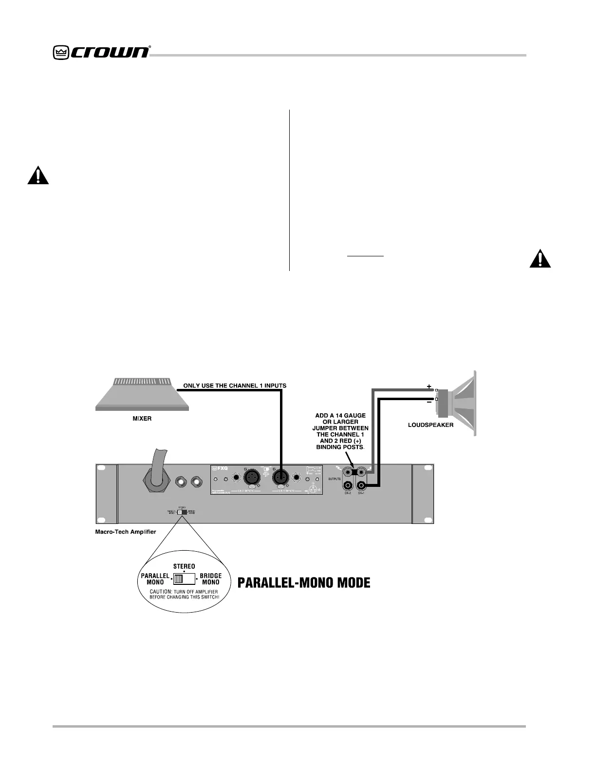
Fig. 3.6 Parallel-Mono Wiring
3.3.3 Parallel-Mono Operation
Parallel-Mono mode is intended for driving loads with a
net impedance of less than 4 ohms. (See Bridge-Mono
if the load is 4 ohms or greater.) Installing the amp in
Parallel-Mono mode is very different from the other
modes and requires special attention.
CAUTION: Do not attempt to operate in Stereo or
Bridge-Mono mode until the Parallel-Mono jumper
is first removed. Failure to do so will result in high
distortion and excessive heating.
To put the amplifier in Parallel-Mono mode, turn it off
and slide the stereo/mono switch to the left (as you face
the back panel). Connect the input signal to Channel 1
only. The Channel 2 input and level control are by-
passed in this mode, so they should not be used.
Note: It is normal for the IOC indicator of Channel 2 to
remain lit in Parallel-Mono mode.
Install a jumper wire between the red binding posts of
both Channel 1 and 2 that is at least 14 gauge in size.
Then, connect the load to the output of Channel 1 as
shown in Figure 3.6. The positive lead from the load
connects to the red binding post of Channel 1 and the
negative lead from the load connects to the black bind-
ing post of Channel 1.
CAUTION: Remove the jumper wire before chang-
ing to Stereo or Bridge-Mono mode.