Macro-Tech
®
602/1202/2402 Power Amplifiers
Page 6
Reference Manual
ILLUSTRATIONS
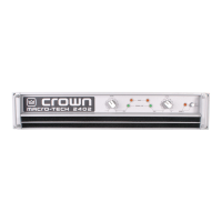
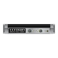
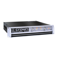
1.1 Macro-Tech Amplifier ................................................................ 7
2.1 Front Panel Controls & Indicators ............................................... 9
2.2 Rear Panel Controls & Connectors .......................................... 10
3.1 Mounting Dimensions .............................................................. 11
3.2 Top View of a Rack-Mounted Unit ............................................ 11
3.3 Proper Air Flow in a Rack Cabinet ........................................... 11
3.4 Stereo Wiring .......................................................................... 12
3.5 Bridge-Mono Wiring ................................................................ 13
3.6 Parallel-Mono Wiring ............................................................... 14
3.7 Unbalanced Input Wiring ......................................................... 15
3.8 Balanced Input Wiring ............................................................. 15
3.9 Balanced and Unbalanced Phone Plugs ................................. 15
3.10 Infrasonic Filter Capacitors ...................................................... 16
3.11 Unbalanced RFI Filters ............................................................ 16
3.12 Balanced RFI Filters ................................................................ 16
3.13 Wire Size Nomograph ............................................................. 17
3.14 Inductive Load (Transformer) Network ..................................... 18
3.15 Loudspeaker Fuse Nomograph ............................................... 19
4.1 Indicators ................................................................................ 20
4.2 Macro-Tech ODEP and Signal/IOC Indicator States ................. 21
4.3 Input Sensitivity and Ground Lift Switches ............................... 23
5.1 Circuit Block Diagram ............................................................. 26
6.1 Macro-Tech 602 Minimum Power Matrix .................................. 30
6.2 Macro-Tech 1202 Minimum Power Matrix ................................ 31
6.3 Macro-Tech 2402 Minimum Power Matrix ................................ 31
6.4 Macro-Tech 602 Maximum Power Matrix ................................. 32
6.5 Macro-Tech 1202 Maximum Power Matrix ............................... 33
6.6 Macro-Tech 2402 Maximum Power Matrix ............................... 33
6.7 Typical Frequency Response .................................................. 34
6.8 Typical Damping Factor .......................................................... 34
6.9 Typical Output Impedance ...................................................... 34
6.10 Typical Phase Response ......................................................... 35
6.11 Typical Crosstalk for the Macro-Tech 602 ................................. 35
6.12 Typical Crosstalk for the Macro-Tech 1202 ............................... 36
6.13 Typical Crosstalk for the Macro-Tech 2402 ............................... 36
7.1 Macro-Tech 602 Power Draw, Current Draw and
Thermal Dissipation at Various Duty Cycles ............................. 37
7.2 Macro-Tech 1202 Power Draw, Current Draw and
Thermal Dissipation at Various Duty Cycles ............................. 38
7.3 Macro-Tech 2402 Power Draw, Current Draw and
Thermal Dissipation at Various Duty Cycles ............................. 38
8.1 PIP2 Adapter Connection ........................................................ 39
8.2 Installing a PIP Module ............................................................ 39
8.3 Installing a PIP2 Module .......................................................... 39
8.4 Installing a Level Control Shaft Lock ........................................ 41