Page 33
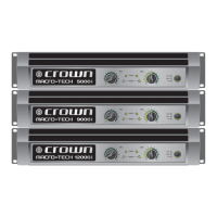
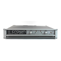
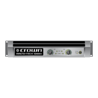
Macro-Tech 5000VZ Power Amplifier
Reference Manual
6 Specifications
The following applies to units in Stereo mode with 8 ohm loads
and an input sensitivity of 26 dB gain unless otherwise speci-
fied. All units have multitap transformers and can be config-
ured for any AC line voltage.
Standard 1 kHz Power: refers to maximum average power
in watts at 1 kHz with 0.1% THD.
Full Bandwidth Power: refers to maximum average power
in watts from 20 Hz to 20 kHz with 0.1% THD.
Performance
Frequency Response: ±0.1 dB from 20 Hz to 20 kHz
at 1 watt (see Figure 6.3).
Phase Response: ±20° from 10 Hz to 20 kHz at 1 watt
(see Figure 6.6).
Signal-to-Noise Ratio: 20 Hz to 20 kHz: Better than 100
dB below full bandwidth power. A-weighted: Better than
105 dB below full bandwidth power.
Total Harmonic Distortion (THD): Less than 0.05% at
full bandwidth power from 20 Hz to 1 kHz increasing
linearly to less than 0.1% at 20 kHz.
Intermodulation Distortion (IMD): (60 Hz and 7 kHz
4:1) Less than 0.05% from 411 milliwatts to full band-
width power.
Damping Factor: Greater than 1,000 from 10 Hz to
400 Hz (see Figure 6.4).
Crosstalk: See Figure 6.7.
Slew Rate: Greater than 30 volts per microsecond.
Voltage Gain: 20:1 ±3% or 26 dB ±0.25 dB at the maxi-
mum level setting. 132:1 ±12% or 42 dB ±1 dB at
0.775 volt sensitivity. 71:1 ±12% or 37 dB ±1 dB at
1.4 volt sensitivity. Also see Section 4.4.
Power
Output Power: See the Minimum Guaranteed Power
table in Figure 6.1 for the output power specifications
under a variety of conditions.
Load Impedance: Safe with all types of loads. Rated
for 2 to 8 ohms in Stereo, 4 to 16 ohms in Bridge-Mono
and 1 to 4 ohms in Parallel-mono mode.
Required AC Mains: 50 or 60 Hz, 100, 120, 200, 208,
230, 240 VAC (±10%). Draws 90 watts or less at idle.
See Section 7 for additional information.
It is extremely important to have adequate AC power
available to the amplifier. Power amplifiers cannot create
energy—they must have the required voltage and cur-
rent to deliver the rated power you expect.
Controls
Compressor: A three-position back panel switch is used
to control each channel’s input compressor. The “fast”
setting provides an attack time of 4 milliseconds and a
release time of 300 milliseconds; the “slow” setting pro-
vides an attack time of 12 milliseconds and a release
time of 600 milliseconds; the “off” setting defeats out-
put-driven compression.
Enable: A front panel push button used to turn the am-
plifier on and off.
Input Ground Lift: A two-position back panel switch
located on the PIP2-FXQ used to isolate the input au-
dio signal grounds from the AC (chassis) ground.
Level: A front panel rotary potentiometer for each chan-
nel with 31 detents used to control the output level.
Loudspeaker Offset Integration: A two-position back
panel switch for each channel used to turn the loud-
speaker protection circuitry on and off. The circuitry
protects against DC, off-center woofer cone movement,
and unwanted subsonic and ultrasonic frequencies.
Sensitivity: A three-position back panel switch for
each channel used to select input sensitivity:
0.775 volts or 1.4 volts for standard 1 kHz power, or a
26 dB voltage gain.
Stereo/Mono: A three-position back panel switch used
to select Stereo, Bridge-Mono or Parallel-Mono mode.
VZ Mode: A four-position switch for each channel in-
side the front panel used to control the switching mode
of the VZ power supplies.
Indicators
Enable: This amber front panel indicator shows the on/
off status of the low-voltage power supply.
Signal/IOC: Each channel has a green front panel in-
dicator that flashes to show amplifier output. If a
channel’s output waveform differs from its input by
0.05% or more, the indicator flashes brightly to show
distortion. This function provides
proof of distortion-free
performance
.
ODEP: Each channel has an amber front panel indica-
tor that shows thermal-dynamic energy reserve. Nor-
mally, each
ODEP
indicator is lit to show available
 Loading...
